TESTING
Maytag Chopper Dishwashers
n
3-9
For Service Technician Use Only
Dispenser Circuit
This test will check the wiring to the dispenser and the
dispenser solenoid or wax motor itself. The following items
are part of the dispenser circuit.
n Harness/Connecon
n Dispenser Solenoid/Wax Motor
n Control Board
Test Procedure
1. Check for obstrucons or mechanical binding prevenng
the dispenser lid from opening. Repair or replace as
necessary.
2. Are all the loads controlled by TRIACs not working?
¾ YES – check for open door switch, TRIAC fuse, or pilot
relay.
¾ NO – just the Dispenser. Go to step 3.
3. Unplug dishwasher or disconnect power.
Strip Circuit – Dispenser
4. Remove outer door panel to access dispenser and r
emove
toe and access panels to access control board.
5. Unplug connector P9 from control board.
6. Check the dispenser solenoid or wax motor (depending
on model) and harness—using an ohmmeter, measure the
resistance between P9-1 and P9-3.
Solenoid:
¾ If the resistance is between 260-300 ohms, the
solenoid valve and harness are good. Go to step 7.
¾ If outside the range, replace the dispenser solenoid.
¾ If an open circuit is detected, check connecons and
harness connuity between control and dispenser. If
good, replace the dispenser solenoid.
Wax Motor:
¾ If the resistance is between 1.4-3.0K ohms, the wax
motor and harness are good. Go to step 7.
¾ If outside the range, replace the dispenser wax motor.
¾ If an open circuit is detected, check connecons and
harness connuity between control and dispenser. If
good, replace the dispenser wax motor.
7. Reconnect P9 to control board.
8. Set voltmeter to AC and connect leads to test-pads P10-
1 & P9-1 on the control board. Plug in dishwasher or
reconnect power.
9. Start the Diagnosc Cycle and at the proper interval
measure for AC out of the control between P10-1 to P9-1.
(Refer to the Dispenser Strip Circuit below.)
IMPORTANT: The Dispenser Solenoid or Wax Motor must
be connected to the control board to measure voltage
accurately!!!
¾ If no AC voltage is measured, replace the control board
and retest.
¾ If 120 VAC is measured and dispenser motor/solenoid
is energized, go to step 10.
10. Unplug dishwasher or disconnect power.
11. Reassemble all parts and panels.
12. Plug in dishwasher or reconnect power and run Diagnosc
Cycle to verify repair.
5
Drain
Dispenser (Detergent and Rinse Aid)
Diverter Valve
Water Softener
Controlled Lower Spray Arm (on some models)
Drying
For Heated Dry, heater is also running. See “Heater” circuit under “Water Heating/Heat Dry and Water Sensing with O.W.I. Sensor (Water/Air/Soil/Temperature)”.
L1
BK
P4-2
P6-3
P10-1
P6-1
P4-1
BR BR WH
N
Use top hole of jumper
W2 as test point for F9.
N.O.
K2
Pilot L1 Relay
(Also see Door
Switch Circuit)
Fuse
F9
Electronic Control
Electronic Control
No test pad on P6-3.
Recommend using test pad on P10-1.
Pin 1
Pin 3
Drain Motor
15
Ω
- 25
Ω
120V, 60 Hz, 45W
Triac
N
WH
P4-1
Pin 1
Pin 3
Electronic Control
Use top hole of jumper
W2 as test point for F9.
N.O.
K2
Pilot L1 Relay
(also see Door
Switch Circuit)
P4-2 P9-3 P9-1
BK
L1
V
V
P10-1
Fuse
F9
Dispenser Wax Motor
1.4K
Ω
- 2.8K
Ω
120V, 60 Hz, 10W
Pin 1
Pin 5
Test pad on P9-3 might crowd P9-1.
Recommend using test pad on P10-1.
Dispenser Solenoid
260
Ω
- 300
Ω
120V, 60 Hz, 17W
Electronic Control
Triac
Electronic Control
Sensor
Input
Switch closes momentarily
and then reopens as the diverter
reaches each potential diverter position.
Diverter
Position
Switch
Electronic Control
No test pad on P11-3.
Recommend using test pad on P11-2.
P11-4
P11-3
P11-2
5V
N.O.
Diverter Sensor
Diverter Motor
L1
BK
P4-2 P7-4
P10-1
P7-6
P4-1
N
WHBU
BU
Pin 3
Pin 1
Use top hole of jumper
W2 as test point for F9.
N.O.
K2
Pilot L1 Relay
(Also see Door
Switch Circuit)
Fuse
F9
Electronic Control
No test pad on P7-4.
Recommend using test pad on P10-1.
Electronic
Control
Triac
Dispenser Valve Motor
1,300
Ω
- 1,600
Ω
120V, 60 Hz, 3W
L1
Regeneration Valve
BK
P4-2
P7-3
P10-1
P7-1
P4-1
N
WH
VV
Use top hole of jumper
W2 as test point for F9.
K2
Pilot L1 Relay
(Also see Door
Switch Circuit)
Fuse
F9
Pin 1
Pin 3
N.O.
Electronic Control
Electronic
Control
Triac
No test pad on P7-3.
Recommend usin
ad on P10-1.
Regeneration Valve
890
Ω
- 1,090
Ω
120V, 60 Hz, 6W
Electronic Control
P11-2
P11-1
RD
RD
(RD)
N.O.
N.O.
5V
(Optional Flowmeter)
Sensor
Input
(Closed when salt low)
Salt Level Reed Switch
39 K
Ω
Salt Level Sensing
Pin 1
Pin 1
Pin 4
Pin 2
Pin 3
Pin 3
Electronic
Control
(RD)
RD
RD
RD
RD
RD
WH
Lower Spray Arm Motor
K2
Pilot L1 Relay
(also see Door
Switch Circuit)
Electronic Control
No test pad on P8-3. Recommend using
test pad on P10-1.
(BU stripe
on plug)
(BU stripe
on plug)
(BU stripe
on plug)
Spray Arm Motor
1,890 - 2,310
Ω
each coil
120 V, 60 Hz, 6 Watts
Controlled Lower Spray Arm Sensor
P1A-17
P1A-19
P1A-20
RD
L1
BK
P4-2 P10-1
P10-3
P4-1
BR BR WH
N
Use top hole of jumper
W2 as test point for F9.
N.O.
K2
Pilot L1 Relay
(Also see Door
Switch Circuit)
Fuse
F9
Electronic Control
Electronic Control
(Red stripe
on plug)
(Red stripe
on plug)
Pin 5
Pin 1
Vent Wax Motor
600
Ω
- 1,800
Ω
120V, 60 Hz, 6W
Electronic Control
Electronic Control
(Red stripe
on plug)
(Red stripe
on plug)
P10-5
P10-4
P11-5
DC Ref
BR
BR
Pin 1 Pin 3
Fan Motor
31K
Ω
- 41K
Ω
5 VDC, 1W
Must measure resistance
with correct polarity and
disconnected from controls.
No test pad on P10-4.
Recommend using test pad on P11-5.
5V
_
+
Vent
Fan
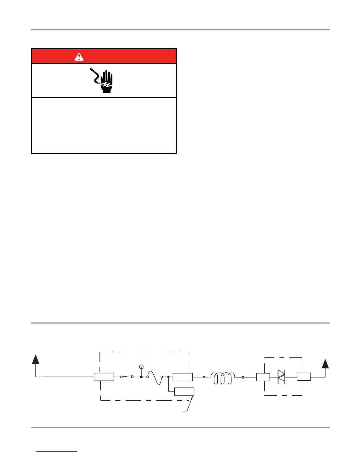
DANGER
Electrical Shock Hazard
Only authorized technicians should perform
diagnostic voltage measurements.
After performing voltage measurements,
disconnect power before servicing.
Failure to follow these instructions can result in
death or electrical shock.
Dispenser Wax Motor
1.4KW - 3.0KW
120V, 60Hz, 10W
 Loading...