TESTING
Maytag Chopper Dishwashers
n
3-15
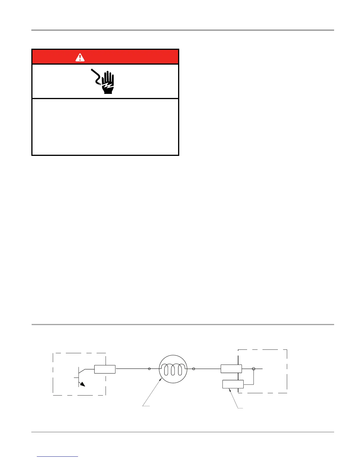
Strip Circuit – Vent Fan
For Service Technician Use Only
DANGER
Electrical Shock Hazard
Only authorized technicians should perform
diagnostic voltage measurements.
After performing voltage measurements,
disconnect power before servicing.
Failure to follow these instructions can result in
death or electrical shock.
Vent Fan (not on all models)
This test will check the wiring to the vent and the vent fan
itself. The following items are part of the vent fan circuit.
n Harness/Connecon
n Vent Fan
n Control Board
NOTES:
Only dishwashers with the Heated Dry opon have a vent and
fan. If moisture is detected between outer and inner door
panels or on cabinets around air inlet located on side of door
panel, check that the vent damper is closing properly using the
Service Diagnosc Cycle.
Also verify that wax motor seal and vent bezel seal are not
pinched or missing. Verify there are no leaks around the vent
bezel seal allowing moisture past the bezel and into the door
panel area.
Test Procedure
1. Check the vent fan and electrical connecons by
performing the Service Diagnosc Cycle. The following
steps assume that this step was unsuccessful.
2. Unplug dishwasher or disconnect power.
3. Remove outer door panel to access control board.
4. Unplug connector P10 from control board.
5. Check the resistance of the fan motor coil. With a
ohmmeter, connect the black lead to P10-5 and the red
lead to P10-4. IMPORTANT: Note measurement polarity.
¾ If the resistance is between 31-41 k-ohms, the fan
motor and harness are good. Go to step 6.
¾ If outside the range, replace the fan motor.
¾ If an open circuit is detected, check connecons and
harness connuity between control and fan motor. If
good, replace the fan motor assembly.
6. Reconnect P10 to control board.
7. With a voltmeter set to DC, connect the black lead to
P10-6 and the red lead to P10-5. IMPORTANT: Note
measurement polarity.
8. Plug in dishwasher or reconnect power.
9. Check for DC voltage from the Control. Start the
Diagnosc Cycle and at the proper interval measure for
+5V DC out of the control between P10 pins 4 & 5.
¾ If +5V DC is measured and fan is running, go to step 10.
¾ If no voltage is measured, replace the control board
and retest.
10. Unplug dishwasher or disconnect power.
11. Reassemble all parts and panels.
12. Plug in dishwasher or reconnect power.
6
Drying
For Heated Dry, heater is also running. See “Heater” circuit under “Wash/Rinse” and “Water Heating/Heat Dry and Water Sensing with O.W.I. Sensor (Water/Air/
Soil/Temperature)” circuits.
Service Diagnostics with Error Codes
Entry sequence: Press START/RESUME to wake up the control panel. Press
any 3 keys in the sequence 1-2-3-1-2-3-1-2-3 with no more than 1 second
between key presses.
NOTE: Some models have replaced the “Clean” LED with “Completed.”
NOTE: Once error codes are extracted Refer to “Service Error Codes Table” to
diagnose and correctly resolve root cause condition.
L1
BK BK
P4-2 P10-1
P10-3
P4-1
BR BR WH
N
N.O.
K2
Fuse
F9
Electronic Control
Electronic Control
Pin 5
Pin 1
Vent Wax Motor
600 Ω - 1,800 Ω
120V, 60 Hz, 6W
Electronic Control
Electronic Control
P10-5
P10-4
P11-5
DC Ref
BR
BR
Pin 1Pin 3
Fan Motor
31KΩ - 41K Ω
5 VDC, 1W
No test pad on P10-4.
Recommend using test pad on P11-5.
5V
_
+
-USTMEASURERESISTANCE
WITHCORRECTPOLARITYAND
DISCONNECTEDFROM
CONTROLS
Use top of hole of jumper
W2 as test point for F9.
Pilot L1 Relay
(Also see Door
Switch Circuit)
(Red stripe
on plug)
(Red stripe
on plug)
(Red stripe
on plug)
(Red stripe
on plug)
DC Fan (not on all models)
L1
BK
P4-2
P7-3
P10-1
P7-1
P4-1
N
WH
BUBU
K2
Fuse
F9
Pin 1
Pin 3
N.O.
Electronic Control
Electronic Control
Tr iac
No test pad on P7-3.Recommend
using test pad on P10-1
.
AC Fan (not on all models)
Use top of jumperW2
as test point for F9
.
AC Fan Motor
115V, 60Hz, 10.2W Ty pical
65Ω -75Ω
Pilot L1 Relay
(Also see Door
Switch Circuit)
DISPLAY TEST - ALL LEDs ON INTERVAL 24
ERROR 1 - MOST RECENT INTERVAL 23
7-SEG will display
FUNCTION code
(F#).
Pause
0.5 sec.
7-SEG will display
PROBLEM code (E#).
Pause
1 sec.
Repeat 3 times
unless
advanced by
Start/Resume
key.
If no error, 7-SEG
will display (F-).
If no error, 7-SEG will
display (E-).
ERROR 2INTERVAL 22
7-SEG will display
FUNCTION code
(F#).
Pause
0.5 sec.
7-SEG will display
PROBLEM code (E#).
Pause
1 sec.
Repeat 3 times
unless
advanced by
Start/Resume
key.
If no error, 7-SEG
will display (F-).
If no error, 7-SEG will
display (E-).
ERROR 3INTERVAL 21
7-SEG will display
FUNCTION code
(F#).
Pause
0.5 sec.
7-SEG will display
PROBLEM code (E#).
Pause
1 sec.
Repeat 3 times
unless
advanced by
Start/Resume
key.
If no error, 7-SEG
will display (F-).
If no error, 7-SEG will
display (E-).
ERROR 4 - OLDESTINTERVAL 20
7-SEG will display
FUNCTION code
(F#).
Pause
0.5 sec.
7-SEG will display
PROBLEM code (E#).
Pause
1 sec.
Repeat 3 times
unless
advanced by
Start/Resume
key.
If no error, 7-SEG
will display (F-).
If no error, 7-SEG will
display (E-).
10-second pause Hi Temp LED will be
on
INTERVAL 19
Press HI TEMP to clear errors.
Hi Temp LED will blink twice to indicate errors have
been cleared. If the Hi Temp key does not respond,
open and close the door to wake up the control
panel. Press HI TEMP to clear errors.
Service Diagnostics Cycle
Turns on loads and checks sensors.
INTERVALS 18-3
SERVICE CYCLE ERROR 1INTERVAL 2
7-SEG will display
FUNCTION code
(F#).
Pause
0.5 sec.
7-SEG will display
PROBLEM code (E#).
Pause
1 sec.
Repeat 3 times
unless
advanced by
Start/Resume
key.
If no error, 7-SEG
will display (F-).
If no error, 7-SEG will
display (E-).
SERVICE CYCLE ERROR 2INTERVAL 1
7-SEG will display
FUNCTION code
(F#).
Pause
0.5 sec.
7-SEG will display
PROBLEM code (E#).
Pause
1 sec.
RepeatTIMES
unless
advanced by
Start/Resume
key.
If no error, 7-SEG
will display (F-).
If no error, 7-SEG will
display (E-).
 Loading...