3-4
n
Maytag Chopper Dishwashers
TESTING
For Service Technician Use Only
Control Board Informaon
SPECIFICATIONS
ELECTRICAL SUPPLY:
(Under Load): 60Hz 120V AC
SUPPLY WATER FLOW RATE:
To ll 2 qt (1.9 L) in 27 seconds, 120 psi maximum, 20 psi
minimum.
SUPPLY WATER TEMPERATURE:
120°F (49°C) (Before starng a cycle, run water from sink
faucet unl hot.)
WATER CHARGE:
1.58 gal. (6.0 L) Approximate
LOWER SPRAY ARM ROTATION:
12 TO 40 rpm
UPPER SPRAY ARM ROTATION:
12 TO 30 rpm
Fuse Service & Resistance Check
F9 = SMALL-TRIAC LOAD FUSE
Check operaon of loads during the Service Diagnoscs cycle.
¾ If any of the TRIAC loads work, F9 Fuse is OK.
¾ If all TRIAC loads fail to work, F9 Fuse could be open. See
Fuse Resistance Check.”
FUSE RESISTANCE CHECK:
1. Unplug the dishwasher or disconnect power.
2. Measure resistance of F9 Fuse.
NOTE: Fuses are on the boom of the Control Board but
can be checked from the top side. See “Control Pinout”
diagram.
¾ If resistance is < 3 Ω, then fuse is OK.
¾ If resistance is > 3 Ω, then fuse is open.
IF THE FUSE IS OPEN:
Inspect and check resistance of all loads on fuse. If any loads
are open, shorted, or have evidence of overheang or pinched
wires, replace loads and/or repair wires.
Component Tesng
TESTING DISHWASHER COMPONENTS FROM THE
CONTROL
Before tesng any of the components, perform the following
checks:
• The most common cause for misdiagnosed control
failure is poor connecons. Therefore, disconnecng,
inspecng and reconnecng wires will be necessary
throughout test procedures.
• All tests/checks should be made with a VOM or DVM
having a sensivity of 20,000 ohms-per-volt DC, or
greater.
• Check all connecons before replacing components,
looking for broken or loose wires, failed terminals, or
wires not pressed into connectors far enough.
• Voltage checks must be made with all connectors
aached to the boards.
• Resistance checks must be made with power cord
unplugged or power disconnected, and with wiring
harness or connectors disconnected from the control.
• The tesng procedures in this secon may require the
use of needle probes to measure voltage. Failure to use
needle probes will damage the connectors.
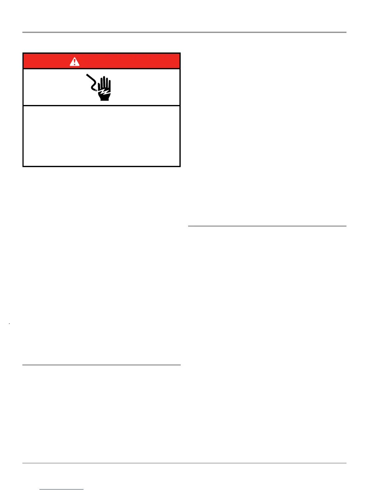
DANGER
Electrical Shock Hazard
Only authorized technicians should perform
diagnostic voltage measurements.
After performing voltage measurements,
disconnect power before servicing.
Failure to follow these instructions can result in
death or electrical shock.

 Loading...