TESTING
Maytag Chopper Dishwashers
n
3-11
For Service Technician Use Only
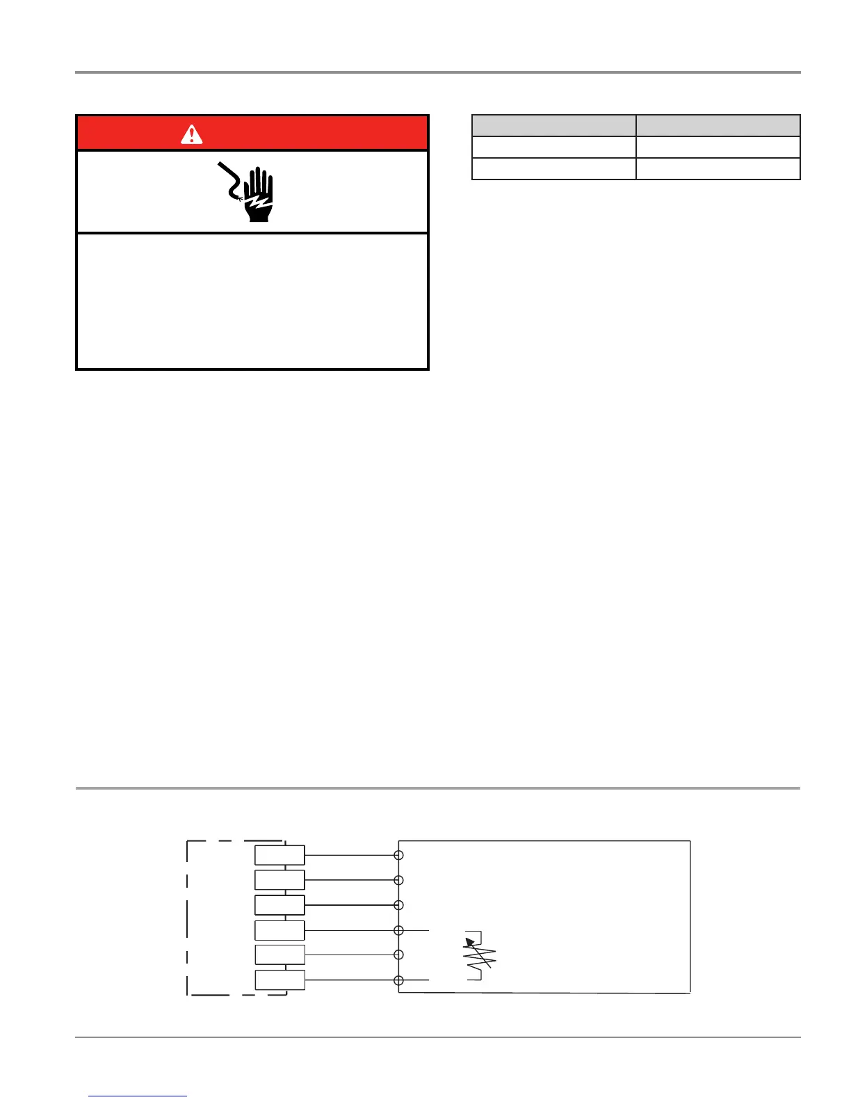
Water Sensing with the OWI Sensor
This test will check the wiring to the OWI (Opcal Water
Indicator), which incorporates the temperature thermistor and
the foam & turbidity sensor. The following items are part of
the water sensing circuit.
n Harness/Connecon
n OWI Sensor
n Control Board
Test Procedure
1. Check the operaon of the OWI Sensor in the Service
Diagnosc Cycle.
2. Unplug dishwasher or disconnect power.
3. Remove outer door panel to access control board.
4. Disconnect P12 from the Control Board.
5. Using an ohmmeter, measure resistance between P12,
pins 1 and 3. The following table provides approximate
room and hot water temperatures and their associated
resistance values.
Strip Circuit – Water Sensing
TEMP °F (°C) RES RANGE k ohms
77° F (25° C) 46 – 52k ohms
140° F (60° C) 11 – 13k ohms
NOTE: All thermistor resistance measurements must be
made while dishwasher is unplugged or disconnected
from power and connector P12 removed from control.
¾ If the thermistor resistance is OK , the thermistor is
good. Go to step 6.
¾ If the thermistor resistance does not agree with the
table, replace the OWI Sensor.
¾ If an open circuit is detected, check connecons and
harness connuity between control and OWI If good,
replace the OWI Sensor.
6. Using an ohmmeter, check P12 -1 to cabinet ground and
P12-3 to cabinet ground.
¾ If no short is indicated, go to step 7.
¾ If either pin indicates connuity to ground (short),
repair or replace wiring harness and retest.
7. Reconnect P12 to control board.
8. Test for 5 VDC—With a voltmeter set to DC, connect the
black lead to P12-2 and the red lead to P12-3.
9. Plug in dishwasher or reconnect power.
10. Start the Diagnosc Cycle and at the proper interval
measure for 5 VDC out of the control between P12-2 and
P12-3.
¾ If 5 VDC is measured the control is funconing, go to
step 11.
¾ If no DC voltage is measured, replace the control board
and retest.
11. Unplug dishwasher or disconnect power.
12. Reassemble all parts and panels.
13. Plug in dishwasher or reconnect power and run Diagnosc
Cycle to verify repair.
4
Control Pinout
Meter Check of Loads and Fuses
Dishwasher Strip Circuits
The following individual circuits are for use in diagnoses. Do not continue with
the diagnosis of the appliance if a fuse is blown, a circuit breaker is tripped, or if
there is less than a 120-volt power supply at the wall outlet.
■ Unplug dishwasher or disconnect power.
■
Perform resistance checks. To check resistance of a component,
disconnect harness leads first.
Door Switch
Wash/Rinse
Water Heating/Heat Dry and Water Sensing with O.W.I. Sensor (Water/Air/Soil/Temperature)
Pump is washing. Control monitors temperature during water heating periods. See “Wash/Rinse” and “Water Sensing with O.W.I. Sensor (Water/Air/Soil/
Te mperature)” circuits.
Fill
(Top)
W2
P5
P6
P7
P8 P9
P10 P11
P12
P13
-4
-3
-2
-1
-2
-1
-1
-6
-9
-1
-6
-1
-6
-1
-5
-6
-1
-3
-5
-1
-2
-4
-6
-1
-3
(OWI)
P12 (Wide Out)
P13
P4
P5
P6
BR
P7
BU
P8
RD
P9
V
P10
BR
P11
RD
P12
YL
Ω of F9 Tr iac Fuse
Electronic Control
Electronic Control
Micro PinMicro Pin
Micro PinMicro Pin
K4
Motor (N) Relay
K3
Heater (L1) Relay
K2
Pilot (L1) Relay
K1
Heater (N) Relay
N.O. N.O. N.O. N.O.
(To Wash Motor)
(To Heater)
(To Wash Motor,
Vent, and Triac Loads)
(To Heater)
N.O.
Door
Switch
Sensing
Input
Ref
P9-5
P10-4
Door
Switch
P9-6
13V
VV
Motor Power
BK
N.O.
TURQ
(LBU)
K2
Pilot L1 Relay
(Also see Door
Switch Circuit)
Electronic Control
P4-2
P5-2
Pin 3
Pin 2
K4
Motor N Relay
(Also see Door
Switch Circuit)
WH
P5-1
P4-1
Sense Resistor
or Jumper
0
Ω
N
L1
V
Y
Y
AUX
Winding
6
Ω
- 10
Ω
CAP
23.5 µF
Run
Winding
3
Ω
- 7
Ω
Motor and Capacitor
(Wash Pump)
120V, 60 Hz, 190W typical
TURQ
(LBU)
Electronic Control
N.O.
L1
BK
Electronic Control
N.O.
K3
Heater L1 Relay
(Also see Door
Switch Circuit)
Hi-Limit
Thermostat
Opens
207°F - 217°F
(97°C - 103°C)
Heater Element
8
Ω
- 30
Ω
120V, 60 Hz
785W Wet
500W Dry
N.C.
P4-2
P4-3
P4-4
P4-1
N
Electronic Control
N.O.
K1
Heater N Relay
(Also see Door
Switch Circuit)
Electronic
Control
P12-6
P12-5
P12-4
P12-3
P12-2
P12-1
Pin 1
Pin 2
Pin 3
Pin 4
Pin 5
Pin 6
Measure NTC resistance at P12-1 and
P12-3 connector disconnected from control.
Turbidity Drive
Foam Drive
OPT Sig
VCC
Ref
NTC
O.W.I. Sensor
Temperature: NTC Thermistor
46K
Ω
- 52K
Ω
at 77°F (25°C)
11K
Ω
- 13K
Ω
at 140°F (60°C)
Heater
BU/RD BU/RD
BU/WH
WH
YL
YL
YL
YL
YL
YL
L1
BK
P4-2 P6-4
P10-1
P6-6
P6-7
P6-9
P4-1
Use top hole of jumper
W2 as test point for F9.
N.O.
K2
Pilot L1 Relay
(Also see Door
Switch Circuit)
Fuse
F9
Electronic Control
Electronic Control
Float
(In normal position,
holds switch closed.)
BR
BR
N.O.
Pin 3 Pin 1
Overfill
Float Switch
No test pad on P6-4.
Recommend using test pad on P10-1.
No test pad on P6-7.
Recommend using test pad on P6-6.
Electronic Control
Float Switch
Input
BR
BR
Pin 3 Pin 1
Triac
Fill Valve
890
Ω
- 1,090
Ω
120V, 60 Hz, 6W
WH
N
DANGER
Electrical Shock Hazard
Only authorized technicians should perform
diagnostic voltage measurements.
After performing voltage measurements,
disconnect power before servicing.
Failure to follow these instructions can result in
death or electrical shock.
 Loading...