TESTING
Maytag Chopper Dishwashers
n
3-17
For Service Technician Use Only
DANGER
Electrical Shock Hazard
Only authorized technicians should perform
diagnostic voltage measurements.
After performing voltage measurements,
disconnect power before servicing.
Failure to follow these instructions can result in
death or electrical shock.
Power Blast (not on all models)
This test will check the wiring to the Power Blast and the
Power Blast wax motor itself. The following items are part of
the Power Blast wax motor circuit.
n Harness/Connecon
n Power Blast Wax Motor
n Control Board
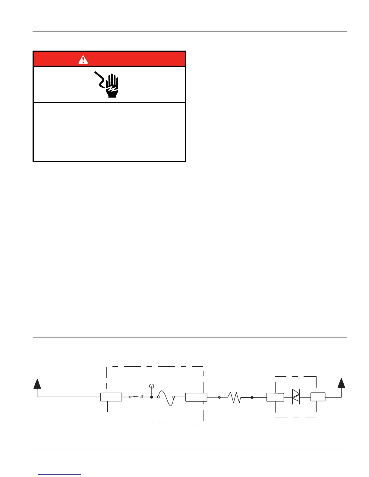
Strip Circuit – Power Blast
Test Procedure
1. Unplug dishwasher or disconnect power.
2. Remove outer door panel to access control board.
3. Unplug connector P7 from control board.
4. Check the Power Blast wax motor and harness—using
an ohmmeter, measure the resistance between P7-4 and
P7-6.
¾ If the resistance is between 600-1800 ohms, the wax
motor and harness are good. Go to step 5.
¾ If outside the range, replace the Power Blast wax
motor.
¾ If an open circuit is detected, check connecons and
harness connuity between control and Power Blast
wax motor. If good, replace the wax motor.
5. Reconnect P7 to control board.
6. Plug in dishwasher or reconnect power.
7. Check for AC voltage from the Control. Start the
Diagnosc Cycle and at the proper interval measure for AC
out of the control between P7-4 to P7-6 using a voltmeter
set to AC.
¾ If no AC voltage is measured, replace the control board
and retest.
¾ If 120V AC is measured and Power Blast wax motor is
energized, go to step 8.
8. Unplug dishwasher or disconnect power.
9. Reassemble all parts and panels.
10. Plug in dishwasher or reconnect power.
5
Fill
Drain
Dispenser (Detergent and Rinse Aid)
Water Softener
Turbozone (not on all models)
L1
BK
P4-2 P6-4
P10-1
P6-6
P6-7
P6-9
P4-1
Use top hole of jumper
W2 as test point for F9.
N.O.
K2
Pilot L1 Relay
(Also see Door
Switch Circuit)
Fuse
F9
Electronic Control
Electronic Control
Float
(In normal position,
holds switch closed.)
BR
BR
N.O.
Pin 3Pin 1
Overfill
Float Switch
No test pad on P6-4.
Recommend using test pad on P10-1.
No test pad on P6-7.
Recommend using test pad on P6-6.
Electronic Control
Float Switch
Input
BR
BR
Pin 3Pin 1
Triac
Fill Valve
890
Ω
- 1,090
Ω
120V, 60 Hz, 6W
W
N
L1
BK
P4-2
P6-3
P10-1
P6-1
P4-1
BR BR W
N
Use top hole of jumper
W2 as test point for F9.
N.O.
K2
Pilot L1 Relay
(Also see Door
Switch Circuit)
Fuse
F9
Electronic Control
Electronic Control
No test pad on P6-3.
Recommend using test pad on P10-1.
Pin 1
Pin 3
Drain Motor
15
Ω
- 25
Ω
120V, 60 Hz, 100W
Triac
N
W
P4-1
Pin 1
Pin 3
Electronic Control
Use top hole of jumper
W2 as test point for F9.
N.O.
K2
Pilot L1 Relay
(also see Door
Switch Circuit)
P4-2 P9-3 P9-1
BK
L1
V
V
P10-1
Fuse
F9
Dispenser Wax Motor
1.4K
Ω
- 2.8K
Ω
120V, 60 Hz, 10W
Pin 1
Pin 5
Test pad on P9-3 might crowd P9-1.
Recommend using test pad on P10-1.
Dispenser Solenoid
280
Ω
- 340
Ω
120V, 60 Hz, 11W
Electronic Control
Triac
L1
Regeneration Valve
BK
P4-2
P7-3
P10-1
P7-1
P4-1
N
W
BUBU
Use top hole of jumper
W2 as test point for F9.
K2
Pilot L1 Relay
(Also see Door
Switch Circuit)
Fuse
F9
Pin 1
Pin 3
N.O.
Electronic Control
Electronic Control
Triac
No test pad on P7-3.
Recommend using test pad on P10-1.
Regeneration Valve
890
Ω
- 1,090
Ω
120V, 60 Hz, 6W
Electronic Control
P11-2
P11-1
R
R
(R)
N.O.
N.O.
5V
(Optional Flowmeter)
Sensor
Input
(Closed when salt low)
Salt Level Reed Switch
39 K
Ω
Salt Level Sensing
Pin 1
Pin 1
Pin 4
Pin 2
Pin 3
Pin 3
Electronic Control
(R)
Electronic Control
K2
Pilot L1 Relay
(Also see door
switch circuit)
Fuse
F9
P4-2
BK
L1
Use top hole of jumper
W2 as test point for F9
N.O.
BU
BU
P7-4
P7-6
P4-1
N
W
Pin 3
Pin 1
Triac
TurboZone Wax Motor
600
Ω
to 1,800
Ω
120V, 60 Hz, 6W
Electronic Control
Power Blast Wax Motor
 Loading...