3-16
n
Maytag Chopper Dishwashers
TESTING
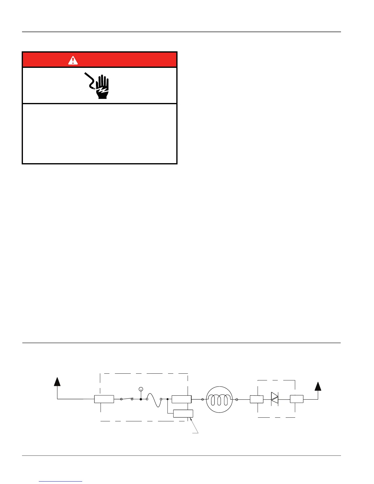
Strip Circuit – AC Fan Motor
For Service Technician Use Only
AC Fan Motor (not on all models)
This test will check the wiring to the AC fan motor and the fan
motor itself. The following items are part of the AC Fan Motor
circuit.
n Harness/Connecon
n AC Fan Motor
n Control Board
Test Procedure
1. Check for fan operaon in the Diagnosc Cycle. The AC fan
should be running during cycles 19, 16, 15, and 3.
2. Are all the loads controlled by TRIACs not working?
¾ YES – check for open door switch, TRIAC fuse, or pilot
relay.
¾ NO – just the diverter valve. Go to step 3.
3. Unplug dishwasher or disconnect power.
4. Remove outer door panel to access control board.
5. Unplug connector P7 from control board.
6. Check the fan motor—using an ohmmeter, measure the
resistance between P7-1 and P7-3.
¾ If the resistance is between 60-80 ohms, the fan motor
and harness are good. Go to step 7.
¾ If outside the range, replace the fan motor assembly.
¾ If an open circuit is detected, check connecons and
harness connuity between control and fan motor. If
good, replace the fan motor assembly.
7. Reconnect P7 to control board.
8. Set voltmeter to AC and connect leads to test-pads P10-
1 & P7-1 on the control board. Plug in dishwasher or
reconnect power.
9. Start the Diagnosc Cycle and at the proper interval
measure for AC out of the control between P10-1 & P7-1.
(Refer to AC Fan Motor Strip Circuit below.)
IMPORTANT: The Fan Motor must be connected to the
control board to measure voltage accurately!!!
¾ If no AC voltage is measured, replace the control board
and retest.
¾ If 120 VAC is measured and the fan is spinning, go to
step 10.
10. Unplug dishwasher or disconnect power.
11. Reassemble all parts and panels.
12. Plug in dishwasher or reconnect power and run Diagnosc
Cycle to verify repair.
6
Service Diagnostics with Error Codes
Entry sequence: Press any 3 keys in the sequence 1-2-3-1-2-3-1-2-3 with no more than 1 second between key presses.
NOTE: Some models have replaced the “CLEAN” LED with “COMPLETE.”
If no error, “Clean” LED stays on for 5 seconds or display shows “F-” or “E-”.
NOTE: Once error codes are extracted, refer to the “Service Error Codes” table to diagnose and correctly resolve the root cause condition.
L1
BK
P4-2
P7-3
P10-1
P7-1
P4-1
N
WH
BUBU
K2
Fuse
F9
Pin 1
Pin 3
N.O.
Electronic Control
Electronic Control
Tr iac
No test pad on P7-3.
Recommend using test pad on P10-1.
AC Fan (not on all models)
Use top of jumper
W2 as test point for F9.
Fan Motor
60
Ω -80Ω
120 V, 60 Hz, 12 Watts
Pilot L1 Relay
(Also see Door
Switch Circuit)
DISPLAY TEST - ALL LEDS ON INTERVAL 28
ERROR 1 - MOST RECENT
SHOW FUNCTION CODE PAUSE SHOW PROBLEM CODE PAUSE
Repeat 3times unless advanced
by Start key.
Count the Clean LED flashes 2 seconds Count Clean LED flashes 5 seconds INTERVAL 27
OR ON DISPLAY MODELS
Read “F#” on Display 0.5 seconds Read “E#” on Display 1 second
ERROR 2
SHOW FUNCTION CODE PAUSE SHOW PROBLEM CODE PAUSE
Repeat 3times unless advanced
by Start key.
Count the Clean LED flashes 2 seconds Count Clean LED flashes 5seconds INTERVAL 26
OR ON DISPLAY MODELS
Read “F#” on Display 0.5 seconds Read “E#” on Display 1 second
ERROR 3
SHOW FUNCTION CODE PAUSE SHOW PROBLEM CODE PAUSE
Repeat 3times unless advanced
by Start key.
Count the Clean LED flashes 2 seconds Count Clean LED flashes 5 seconds INTERVAL 25
OR ON DISPLAY MODELS
Read “F#” on Display 0.5 seconds Read “E#” on Display 1 second
ERROR 4 - OLDEST
SHOW FUNCTION CODE PAUSE SHOW PROBLEM CODE PAUSE
Repeat 3times unless advanced
by Start key.
Count the Clean LED flashes 2 seconds Count Clean LED flashes 5 seconds
INTERVAL 24
OR ON DISPLAY MODELS
Read “F#” on Display 0.5 seconds Read “E#” on Display 1 second
10 seconds pause Hi Temp LED will be on INTERVAL 23
Press Hi Temp key to clear errors. Hi Te mp LED will blink twice to indicate errors have been cleared.
Service Diagnostics Cycle
INTERVAL 22-3
Turns on loads and checks sensors.
SERVICE CYCLE ERROR 1
A tone will play when service error code 1 is displayed
SHOW FUNCTION CODE PAUSE SHOW PROBLEM CODE PAUSE
Repeat 3times unless advanced
by Start key.
Count the Clean LED flashes 2 seconds Count Clean LED flashes 5 seconds INTERVAL 2
OR ON DISPLAY MODELS
Read “F#” on Display 0.5 seconds Read “E#” on Display 1 second
S
ERVICE CYCLE ERROR 2
SHOW FUNCTION CODE PAUSE SHOW PROBLEM CODE PAUSE
Repeat 3times unless advanced
by Start key.
Count the Clean LED flashes 2 seconds Count Clean LED flashes 5 seconds INTERVAL 1
OR ON DISPLAY MODELS
Read “F#” on Display 0.5 seconds Read “E#” on Display 1 second
DANGER
Electrical Shock Hazard
Only authorized technicians should perform
diagnostic voltage measurements.
After performing voltage measurements,
disconnect power before servicing.
Failure to follow these instructions can result in
death or electrical shock.
 Loading...