McHale Orbital Round Bale Wrapper
75
This completes adapting the machine for fitting a side-tip assembly, which is only
necessary the very first time.
Instructions from here on (10 - 13) apply to installing or removing the side-tip assembly to
the machine.
NOTE:
Removal is in reverse order of installation.
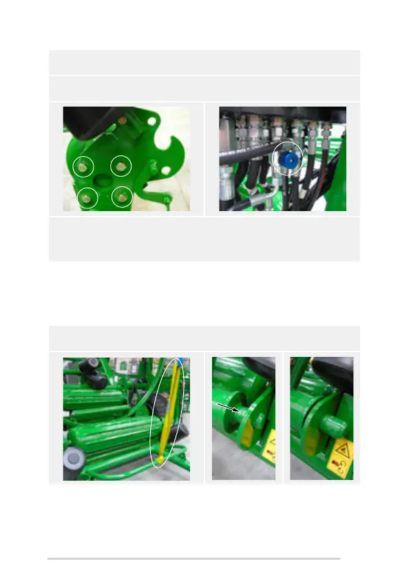
7. To fit the left mounting bracket (ARC00394) to the idle end of the roller, remove
the four M16 nuts and bolts.
8. Fit the bracket, using four M16 x 55 bolts (CFA00349) and nyloc nuts. (H) Ensure
bolts are tightened fully.
9. Fit the flow-restrictor valve (CVA00276) under the main hydraulic valve, as
shown, by removing the cradle supply hose, mounting valve, fittings and
washers. (P) Once the machine is up and running, this valve can be adjusted to
give the desired lowering speed for the rear cradle and side-tip combination.
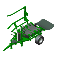
10.
Using suitable lifting gear (
J
), place the side-tip frame assembly down into the
mounting brackets. First engage the right main pivot into the right cradle bracket. (
M
)