QUICK START MANUAL Document reference MAVM600MK2MPS-QS/E
VM600
Mk2
machinery protection system (MPS) Edition 2 - February 2021
1-12
Connecting power
INTRODUCTION TO THE VM600
Mk2
MACHINERY PROTECTION SYSTEM (MPS)
1.3.1 Front panels
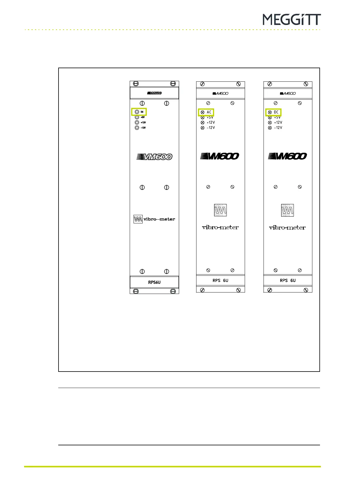
Figure 1-5 shows the panels of RPS6U rack power supplies with different inputs: AC or DC.
NOTE: For a VM600
Mk2
/VM600 system rack (ABE04x) with two RPS6U rack power
supplies connected to two external mains supplies, if one of the external mains
supplies is not connected/operating, the +5V LED on the RPS6U connected to that
(non-operating) external mains supply can still show yellow even though that
particular RPS6U’s +5 V output is not operating normally.
(This incorrect 5V LED indication is due to reverse/leakage current across an
ORing diode used to connect the +5 V outputs from both RPS6Us.)
Figure 1-5: Front panels for the different versions of the RPS6U rack power supply
(a) Panel of later (higher-power)
version of the RPS6U rack
power supply
(b) Panels of earlier (original)
version of the RPS6U rack power supply:
AC-input version (left) and
DC-input version (right)
IN, AC or DC LED:
Green indicates that the
external mains supply is
present and is within the
normal range.
This LED is on when
the RPS6U is operating
normally.
+5V, +12V and −12V LEDs:
Yellow indicates that the
corresponding internal
supply voltage is being
generated and is within the
normal range.
These LEDs are on when
the RPS6U is operating
normally.
(AC-input version) (DC-input version)
 Loading...
