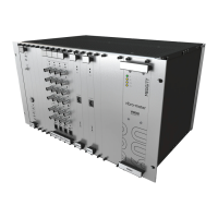
Document reference MAVM600MK2MPS-QS/E QUICK START MANUAL
Edition 2 - February 2021 VM600
Mk2
machinery protection system (MPS)
1-19
Connecting to a computer
INTRODUCTION TO THE VM600
Mk2
MACHINERY PROTECTION SYSTEM (MPS)
1.7 Connecting to a computer
The MPC4
Mk2
+IOC4
Mk2
machinery protection and condition monitoring module has one
system communication interface available via the “LAN” connector on the front panel of the
MPC4
Mk2
module (front of VM600
Mk2
/VM600 rack). See Figure 2-1.
This system communication interface is a Ethernet interface (10/100BASE-TX (up to
100 Mbps)) that is used for all communications with the MPC4
Mk2
+IOC4
Mk2
module. The
MPC4
Mk2
module supports a proprietary TCP/IP-based protocol that communicates with the
VibroSight and VibroSight Protect software running on an external computer.
Standard Ethernet cables (Cat 5 or better) can be used for networking between a VM600
Mk2
machinery protection system (MPS) and network switches or computers.
For a VM600
Mk2
machinery protection system (MPS) consisting of a single
MPC4
Mk2
+IOC4
Mk2
module, or when working with a single MPC4
Mk2
+IOC4
Mk2
module,
the MPC4
Mk2
module can be connected directly to a VibroSight computer or connected
indirectly via a network switch (see Figure 1-6 (a) or (b)).
For a VM600
Mk2
machinery protection system (MPS) consisting of multiple
MPC4
Mk2
+IOC4
Mk2
modules, the MPC4
Mk2
modules are connected together using one or
more network switches (or equivalent) before being connected to a VibroSight computer
(see Figure 1-6 (b)).
1.8 Software configuration
The modules in a VM600
Mk2
machinery protection system (MPS) must be software
configured before the system can be used.
While the majority of settings are normally configured in the factory before delivery, the user
is nevertheless able to modify certain parameters using the VibroSight Protect software and
any associated hardware jumpers on the IOC4
Mk2
and RLC16
Mk2
modules, if required.
NOTE: Refer to the VibroSight software release notes and VibroSight help for further
information on the software.
In general, the VibroSight Protect software is used for software configuration as follows:
• To configure the system properties for the VM600
Mk2
/VM600 rack.
For example, type of rack (system rack (ABE04x) or slimline rack (ABE056)); type and
organisation of power supplies (AC and/or DC input, rack power supply redundancy);
type (MPC4
Mk2
+IOC4
Mk2
or RLC16
Mk2
), number (up to 12) and location (rack slot
number/position) of VM600
Mk2
modules.
Global system properties are configured and summarised on the Layout tab of
VibroSight Protect.
• To configure the settings for the VM600 Mk2 modules (MPC4
Mk2
+IOC4
Mk2
and
RLC16
Mk2
) in the VM600
Mk2
/VM600 rack.
For example, for a MPC4
Mk2
+IOC4
Mk2
module, network settings (IP address);
sensor/measurement chain, processing and alarms for each channel (dynamic and
auxiliary); logical functions; relays (user-configurable and common-circuit fault);
analog outputs.

 Loading...