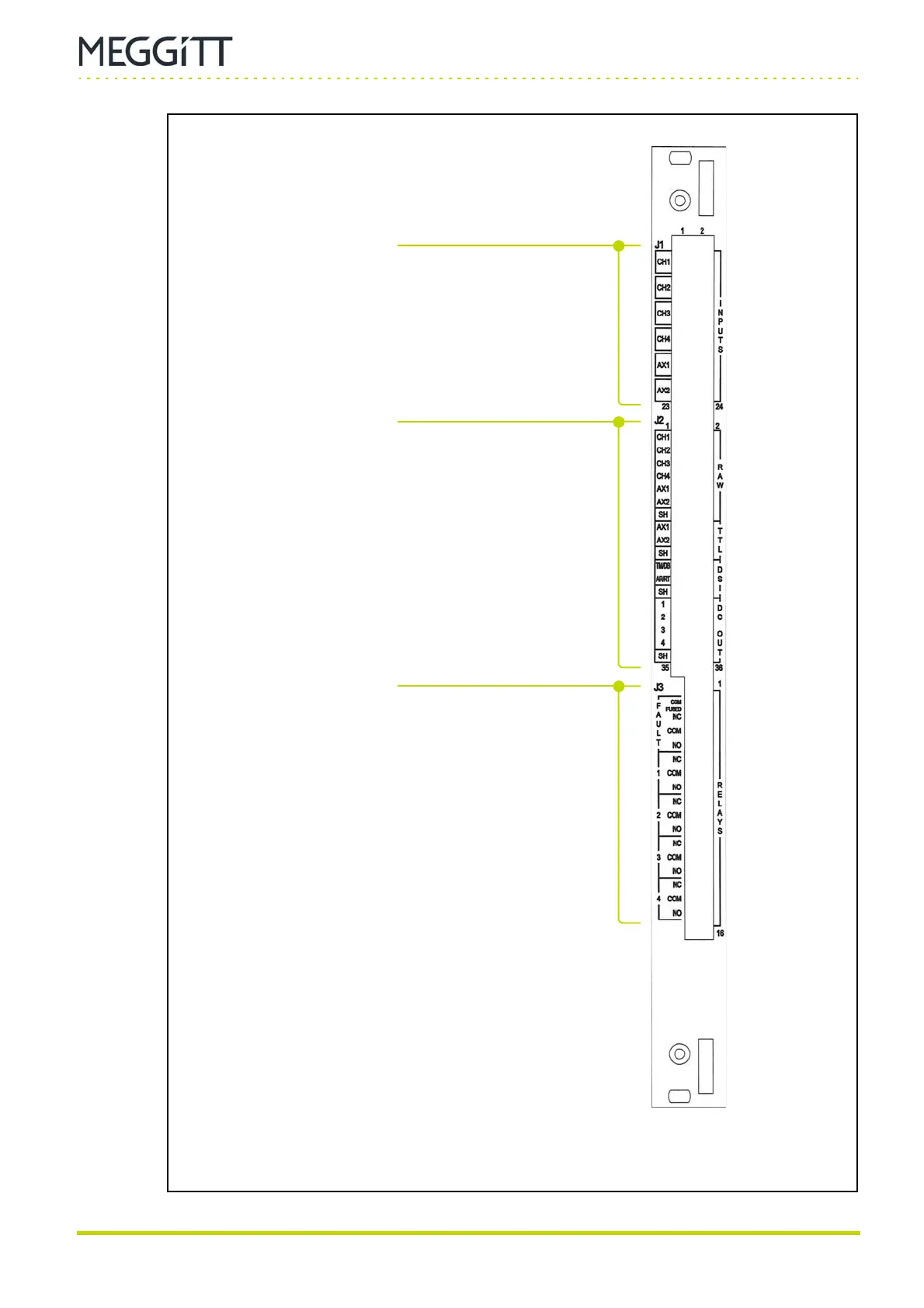
Figure 2-3: IOC4
Mk2
panel (rear of VM600
Mk2
/VM600 rack)
J1 connector
24-pin S2L connector (male).
Compatible with 24-pin B2CF/B2L plug-in connectors
(female) with spring connections.
Connections:
• Inputs (analog signals) for the dynamic channels (CH1
to CH4) and the auxiliary channels (AX1 and AX2).
J2 connector
36-pin S2L connector (male).
Compatible with 36-pin B2CF/B2L plug-in connectors
(female) with spring connections.
Connections:
• Inputs and ground reference (digital signals) for the DSI
control signals (AB, AR and TM).
• Outputs (buffered “raw” analog signals) for the dynamic
channels (CH1 to CH4) and the auxiliary channels (AX1
and AX2).
• Outputs (digital (pulse train) signals (TTL-level)) for the
auxiliary channels (AX1 and AX2).
• Outputs (analog signals) for the analog DC outputs.
J3 connector
16-pin connector (male).
Compatible with 16-pin MC/SCF plug-in connectors
(female) with screw-terminal connections.
Connections:
• Outputs (contacts) for the common circuit fault relay
(FAULT) and the user-configurable relays (RL1 to RL4).
 Loading...
