148
oscillation of the system. Usually, it is better to adjust the proportional gain P first to increase the P value
as larger as possible while ensuring no oscillation to the system, and then adjust the integral time I to
ensure that the system has quick response characteristics and small overshoot.
Let the output of the speed regulator (ASR) pass the delay filter once to get the torque current reference.
P05.02 and P05.06 are the time constants of the low-speed and high-speed loop output filters
respectively. Generally, no modification is needed.
As default, parameters of P05.08~P05.09 are the speed loop low-speed PI parameters of motor 2. When
the running frequency of motor 2 is less than the ASR switching frequency 3 (P05.10), P05.08~P05.09
are enabled. The speed loop high-speed PI parameters of motor 2 are the same as that of motor 1
(P05.04~P05.05).
When only motor 1 is in control, P05.08~P05.09 can be used as the speed loop PI parameters of motor
1 when its running frequency is higher than the ASR switching frequency 3 (P05.10).
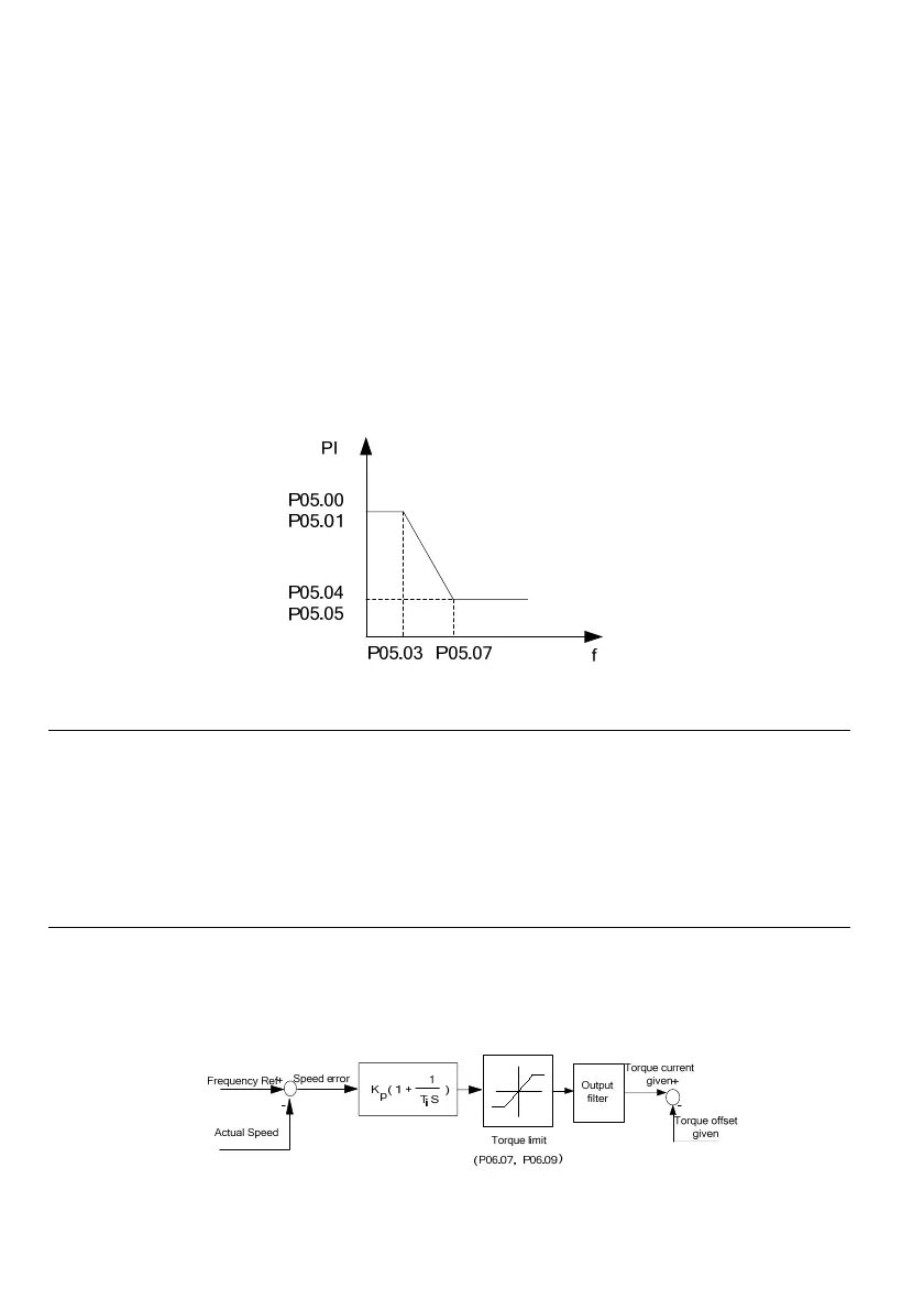
Fig. 6-19 Schematic diagram of PI parameters
Note
1. If the PI parameter is not selected properly, the over-voltage fault may occur after the system is started to
reach the high speed quickly (if no external braking resistor or brake unit is connected). This is caused by the
energy feedback produced in the system regenerative braking while decelerating after the overshoot. It can
be avoided by adjusting the PI parameter.
2. When two motors are switched for use, do not set parameters of P05.08~P05.09 to be the ultra high-speed
section PI of motor 1.
In the vector control mode, the speed response features of the vector control can be changed by setting
the proportional gain P and integral time I of the speed regulator.
1. Component of speed regulator (ASR)
As shown in Fig.6-20, K
P
is the proportional gain P and T
I
is the integral time I.
Fig. 6-20 Simple diagram of the speed regulator
 Loading...