184
Percentage
Pulse
frequency
0
P09.30
P09.30
2
100%
-100%
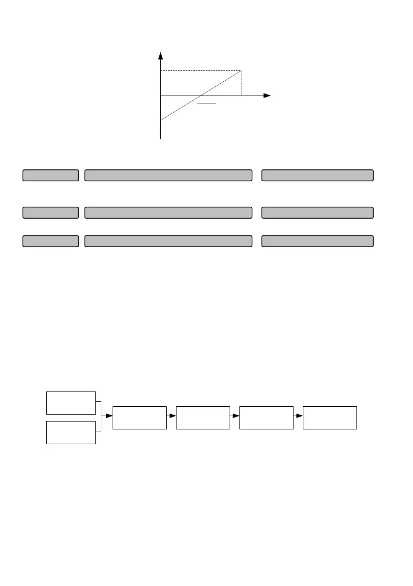
Fig. 6-44 Central point mode 2
This function code defines the filtering time of the output pulse. The longer the filtering time is, the slower
the output pulse frequency change rate will be.
It is used together with the No. 20 function of the digital output terminal.
This function code is relative to the maximum output frequency P02.15. It is used together with No. 10
function of the digital output terminal.
6.11 Analog input/output terminal parameters (Group P10)
The analog input AI1~AI3 and pulse input can be used as different channel references. For the function
selection of the analog input channel, please refer to the setting of the function code of Group P10.01.
For the function selection of the pulse input, please refer to the setting of the X7 and X8 terminal input
functions. For example, when AI1, AI2, AI3 or the pulse frequency (PULSE) input is selected as the
frequency reference channel, the relationship between the reference frequency and the set frequency is
as shown in Fig. 6-45 (take AI1 as the main frequency reference channel):
P02.04
P10 .01
Filter
Curve selection
P10 .05
Curve set
Set frequency
~P10.04P10.02
~P10.21P10.06
Fig. 6-45 The relationship between the reference channel input and the set frequency
After the analog reference signal is filtered, the relationship with the set frequency is determined by the
linear 1, linear 2 or curve 1. The linear 1 is defined by P10.06~P10.09. The linear 2 is defined by
P10.10~P10.13 and the curve 1 is defined by P10.14~P10.21. Take the set frequency as an example,
both can realize the positive action and reverse action independently, as shown in Fig. 6-46.
Zero-speed threshol
0.0~100.0% (1.0%)P09.34
Flux detection value 10.0~100.0%(100.0%)P09.33
Pulse output filtering time 0.00~10.00s (0.05s)P09.32
 Loading...