185
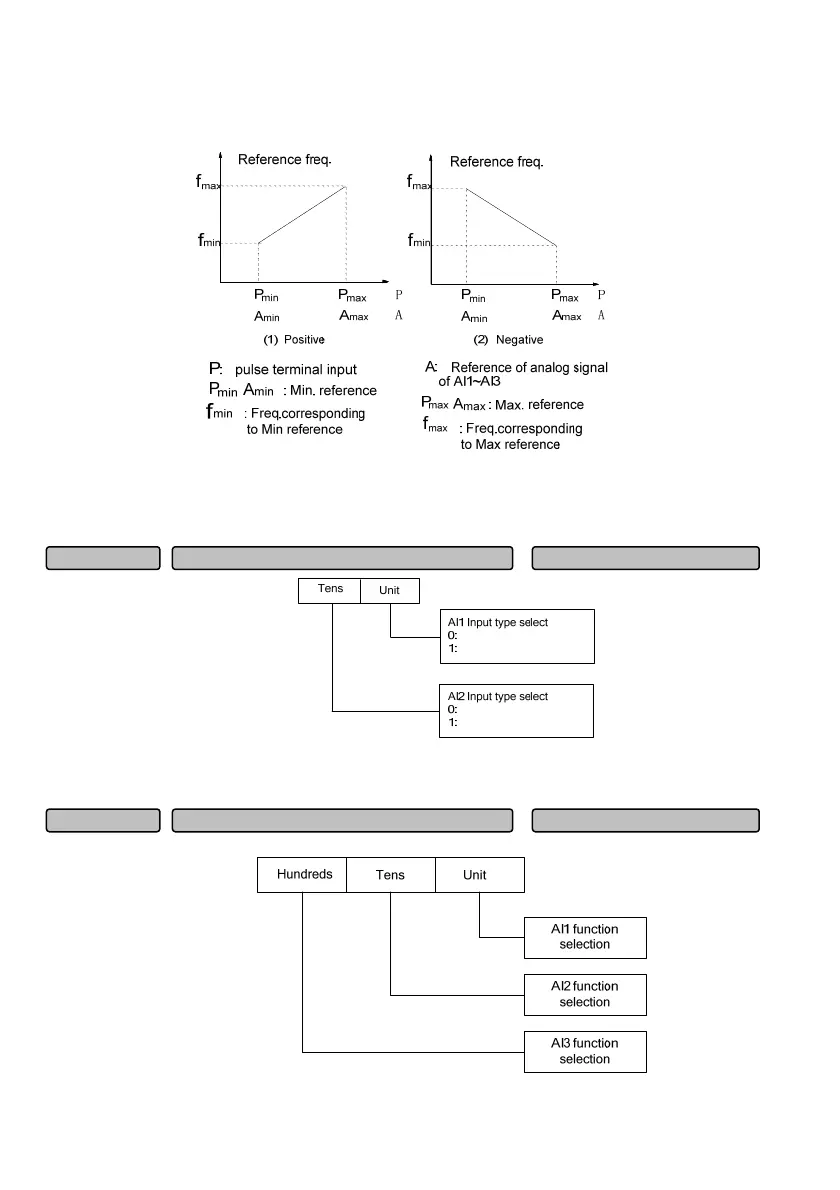
The Fig. 6-46 shows the correspondence when the inflection point is set on the curve determined by the
maximum and minimum reference point. If the inflection point is set on other positions, it has other flexible
correspondence, please refer to the example below for details.
Fig. 6-46 Analog output frequency feature curve
When the analog input A is 100
%, it corresponds to 10V or 20mA; when the pulse frequency P is 100%,
it corresponds to the maximum input pulse frequency defined by P09.11 or P09.12.
20mA~0
10V~10V-
20mA~0
10V~10V-
Fig. 6-47 Analog input type selection
This function code is used for selecting the analog input type and range of AI1 and AI2.
Fig. 6-48 Analog input function selection
Analo
AI function selection 000~EEEH
000H
P10.01
Analo
in
ut t
e selection 00~11
00
P10.00
 Loading...