215
6.17 Keyboard display setting parameters (Group P16)
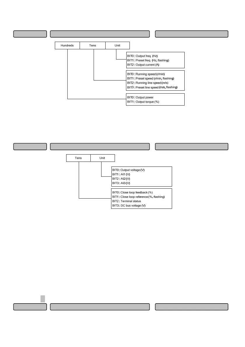
Fig. 6-76 Setting of LED display parameter selection 1 when running
P16.00 and P16.01 define the parameters that LED can display when the drive is in running state.
When 0 is selected for the BIT bit, it indicates that the parameter is not displayed.
When 1 is selected for the BIT bit, it indicates that the parameter is displayed.
Fig. 6-77 Setting of LED display parameter selection 2 when running
For the displayed terminal status, the terminal status adopts the defined value of the LED digital diode
through the multi-functional input terminal X1~X8 status (bit0~bit7 corresponding to X1~X8) and output
terminal Y1, Y2, RO1 and RO2 (bit12~bit15 corresponding to Y1, Y2, RO1 and RO2) to indicate the
status of each function terminal. For instance, when X1, X2 terminals are closed while other terminals are
disconnected, it indicates that the terminal state value is 03H.
Note: When the rotating speed or the line speed is displayed, it can be directly changed by pressing ∧
or
∨ key (no need to switch into the frequency state).
When 0 is selected for all the P16.00 and P16.01 BIT bits, the output frequency will be displayed by
default.
In the running parameter display state, the parameters for display can be switched in turn by pressing the
shift key 》.
LED dis
la
arameter selection when sto
0~FFFH
009
P16.02
LED dis
la
arameter selection 2 when runnin
0~FFH
00
P16.01
LED dis
la
arameter selection when runnin
0~3F7H
007
P16.00
 Loading...