193
P10.29~P10.31 are used for correcting the zero offset of analog inputs AI1, AI2 and AI3.
Take AI1 as an example to introduce zero offset correction.
AI1 is used as voltage type signal, when the input signal is 0V, observe AI1 value P01.20, if P01.20 is
non-zero value at this time, it indicates that AI1 has zero offset, you need to enter the value which has
equal absolute value but opposite sign with P01.20 in P10.29. If P01.20 = 0.01V, then set P10.29 =
-0.01V.
6.12 Auxiliary function parameters (Group P11)
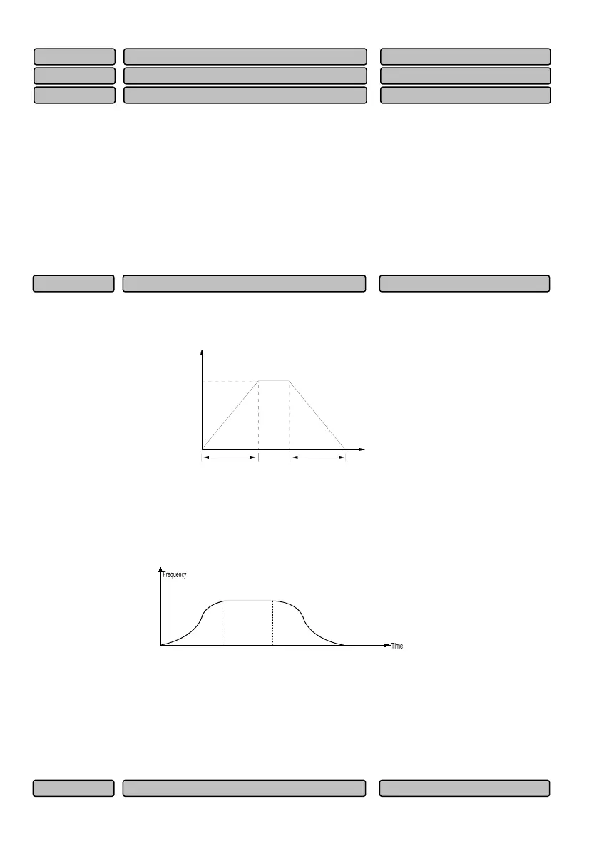
0: Linear acceleration/deceleration
The output frequency is decreased or increased according to constant slope, as shown in Fig. 6-56.
Frequency
Time
f
max
t
1
t
2
Fig. 6-56 Linear acceleration/deceleration
1: S curve acceleration/deceleration
The output frequency is decreased or increased according to the S curve, as shown in Fig. 6-57.
Fig. 6-57 S curve acceleration/deceleration
The speed setting value is in the S curve status at the beginning of the acceleration and when it reaches
the desired speed, and at the beginning of the deceleration and when it reaches the desired speed. Thus,
the acceleration and deceleration can be smooth and there is less impact. The S curve
acceleration/deceleration mode is applicable to the start and stop of carrier of transportation and
transmission, such as the elevator, conveyor, etc.
AI3 zero offset correction -1.00~1.00
0.00V
P10.31
AI2 zero offset correction -1.00~1.00
0.00V
P10.30
AI1 zero offset correction -1.00~1.00
0.00V
P10.29
Acceleration/deceleration time unit 0~2
1
P11.01
Acceleration/deceleration mode selection 0~1
0
P11.00
 Loading...