267
Appendix 2 Braking Components
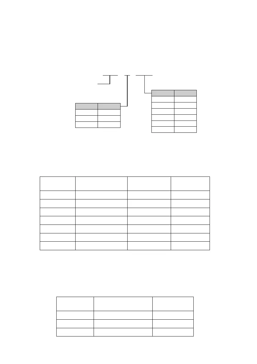
1. Definition of external braking unit model
DBU -X -XXX
Braking
unit
Code Voltage
2 AC 200V
4 AC 400V
6 AC 600V
Code Power
015 15kW
022 22kW
030 30kW
045 45kW
110 110kW
220 220kW
AC voltage level
Power of matched
drive when ED10%
Attached Fig. 2-1 Definition of brake unit model
Note: ED10% in the above figure means the brake utilization rate is 10%.
2. External brake module configuration (configuration for working conditions of 10% braking utilization rate
and 760V braking action voltage)
Attached Table 2-1 External brake module configuration
Motor rated
power (kW)
Brake unit model and
parallel number
Brake resistor
configuration
Braking torque (%)
90 DBU-4045C*2 9600W/13.6Ω*2
120
110 DBU-4030D*3 6000W/20Ω*3
100
132 DBU-4045C*3 9600W/13.6Ω*3
130
160 DBU-4220B*1 40kW /3.4Ω*1
140
200 DBU-4220B*1 60KW /3.2Ω*1
120
220 DBU-4220B*1 60KW /3.2Ω*1
110
280 DBU-4300*1 60KW/2Ω*1
110
Note: The above configuration suggestions are suitable for most applications. For specific applications or
other braking working conditions, please consult our company.
3. Brake resistor configuration of the built-in brake unit drive (The application working condition is 10% braking
utilization rate)
Attached Table 2-2 Brake resistor accessory
Motor rated power
(kW)
Braking resistor model
Braking torque (%)
0.75 70W/750Ω 120
1.5 260W/400Ω 120
2.2 260W/250Ω 140
 Loading...