165
Time
t
1
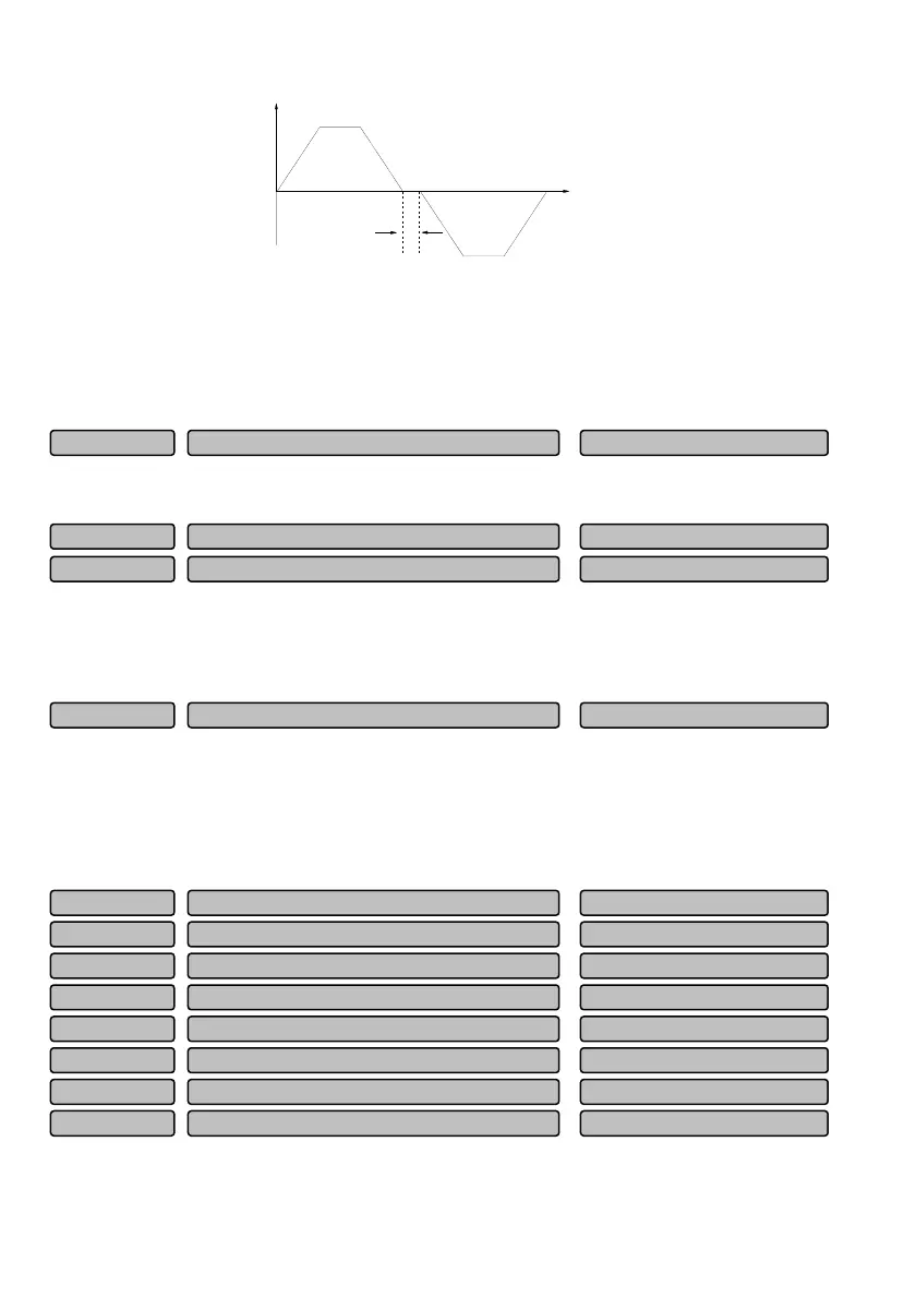
Output
frequency
Fig. 6-30 FWD/REV dead time
For some production equipment, reverse running may cause equipment damage. This function can be
used to prevent the reverse running.
The waiting transition time at the output of zero frequency when the drive switches from forward running
to reverse running (or from reverse running to forward running), as t
1
shown in Fig. 6-30.
0: Switch once over the zero frequency
1: Switch once over the startup frequency
The use ratio of dynamic braking P08.21 and the braking startup voltage P08.22 are only applied to the
drive with built-in braking unit.
Action voltage of braking unit can be selected by adjusting P08.22. The system can be stopped rapidly by
the dynamic braking with the appropriate action voltage.
When the input signal of the emergency stop terminal (NO. 60 terminal function) is enabled, the drive
begins to decelerate to stop. The deceleration time is determined by P08.23. When it is set as 0s, the
drive will stop within the shortest deceleration time.
6.10 Digital input/output parameters (Group P09)
In
ut terminal X8
0~95 (0)P09.07
In
ut terminal X7
0~95 (0)P09.06
In
ut terminal X6
0~95 (0)P09.05
In
ut terminal X5
0~95 (0)P09.04
In
ut terminal X4
0~95 (0)P09.03
In
ut terminal X3
0~95 (0)P09.02
In
ut terminal X2
0~95 (2)P09.01
Input terminal X1
0~95 (1)P09.00
Deceleration time for emergency stop
0.00~100.00s
0.00s
P08.23
Braking startup voltage
700~780V
750V
P08.22
Use ratio of dynamic
raking
0.0~100.0%
00.0%
P08.21
FWD/REV switching mode
0~1
0
P08.20
 Loading...