213
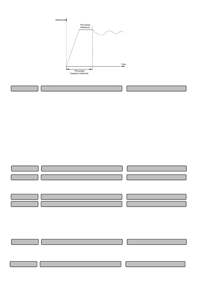
Fig. 6-74 Schematic diagram of PID preset frequency running
Unit place: PID feedbacks the fault detection selection
0: Continue to run, no alarm
1: Continue to run and display “AL.FbL” (feedback lost) or “AL.Fbo” (feedback exceeding limit)
2: Coast to stop and display “Er.FbL” (feedback lost) or “Er.Fbo” (feedback exceeding limit)
Note: Once a PID feedback fault occurs (feedback lost or feedback exceeding limit), the multi-functional
output terminals of the corresponding “feedback loss” and “feedback exceeding limit” will output.
Tens place: PID limit setting error processing selection
0: Continue to run, no alarm
1: Continue to run and display “AL.PIL”
2: Coast to stop and display “Er.PIL”
When the set PID lower limit is greater than PID upper limit , wrong PID limit value setting will occur.
When the feedback signal is less than the detection value set by P14.26 and its time exceeds the time set
by P14.27, then PID feedback is considered as “loss”.
When the feedback signal is greater than the detection value set by P14.28 and its time exceeds the time
set by P14.29, then PID feedback is considered as “exceeding limit”.
6.16 Communication parameters (Group P15)
0: Modbus protocol
1: Reserved
PID feedback exceedin
limit detection time 0.0~25.0s
1.0s
P14.29
PID feedback exceedin
limit detection value 0.0~100.0%
100.0%
P14.28
PID feedback lost detection time 0.0~25.0s
1.0s
P14.27
PID fault detection selection 00~22H
00
P14.25
PID feedback loss detection value 0.0~100.0
0.0%
P14.26
Protocol selection 0~1
0
P15.00
Communication confi
uration 0~155H
001
P15.01
 Loading...