143
This function code displays the initial angle for Z pulse of the synchronous motor currently used.
This function code displays the type of the synchronous motor currently used.
“0” represents SMPM.
“1” represents IPM.
6.5 Encoder parameters (Group P04)
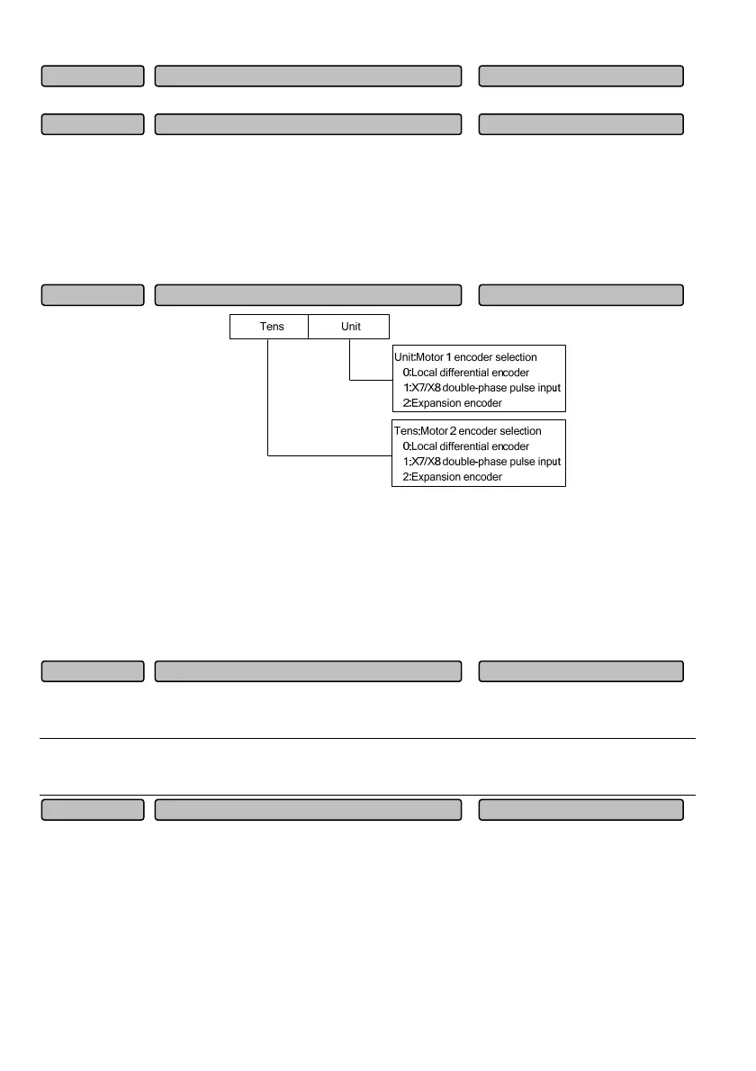
Fig. 6-14 Speed feedback encoder selection
The drive can accept three speed input modes, including the local differential encoder, X7/X8
double-phase pulse input and the expansion encoder. The motor can accept anyone of the three modes
as the speed test mode. However, once a speed test mode is selected by one motor, the other motor can
only select from the other two modes. If both motors select the same speed test mode, the system will
report the Er.PST fault. X7/X8 double-phase pulse input can only be used for the closed loop vector
control of the asynchronous motor.
The parameters of the local encoder are set according to the number of pulses per revolution (PPR) of
the pulse encoder (PG) selected.
Note
When there is any speed sensor, be sure to properly set this parameter, otherwise, the motor cannot operate
normally.
Local encoder parameters
0: A before B 1: B before A
When the motor is running forward, A is before B. When the motor is running reversely, B is before A.
When the wiring sequence between the drive interface board and the PG has the same direction with
the wiring sequence between the drive and motor, the set value shall adopt “0” (FWD), otherwise, it shall
adopt “1” (REV). The correspondence relation between the wiring directions can be conveniently
adjusted by changing this parameter, and you do not need to rewire the relevant unit.
Rotation direction of local PG 0~1 (0)P04.02
Number of pulses per revolution of local PG 1~10000 (1024)P04.01
Speed feedback encoder selection 00~22H(10H)P04.00
Synchronous motor type selection 0~1 (0)P03.28
Initial angle of encoder Z pulse 0~FFFFH (0)P03.27
 Loading...