241
In the above table, the check code is the LRC checksum, which is equivalent to the complement of
“05+06+02+01+0x0F+0xA0”.
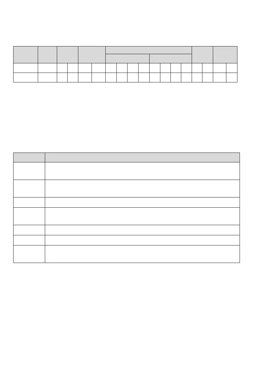
Response frame:
Frame
head
Slave
address
Command
code
Data
Check
code
Frame trail
Register address Written content
Character : 0 5 0 6 0 2 0 1 0 F A 0 4 3 CR LF
ASCII 3A
30 31 30 36 30 32 30 31 30 46 41 30 34 33 0D 0A
With the function codes, the drive can set different response delays to meet the specific application demands
of various host stations. For the RTU mode, the actual time of response delay shall be not less than the
interval of 3.5 characters; and for the ASCII mode, the actual time of response delay shall be not less than
1ms.
5. Protocol functions
The main function of Modbus is reading/writing parameters. Different command codes determine different
operation requests. The Modbus protocol of MV600 drive supports the operations as shown in the following
table:
Command code Meaning
0x03
Reading the drive parameters, including function code parameters, control parameters and status
parameters.
0x06
Change the single 16-byte function code parameter or control parameter of the drive, and the parameter
value will not be saved after power off.
0x08
Line diagnosis.
0x10
Change multiple function code or control parameters of the drive, and the parameter value will not be saved
after power off.
0x41
Change the single 16-byte function code parameter or control parameter of the drive, and the parameter
value will be saved after power off.
0x42 Manage the drive function codes.
0x43
Change multiple function code or control parameters of the drive, and the parameter values will be saved
after power off.
All the function code parameters, control parameters and status parameters of the drive are mapped as the
read/write registers of Modbus. The read/write features and range of the function code parameter follow the
drive user manual. The group number of the drive function code is mapped as the high byte of the register
address and the group internal index (i.e. the serial number of the parameter in the group) is mapped as the
low byte of the register address. The control parameter and status parameter of the drive are virtual function
code groups of the drive. The correspondence between the group numbers of the function codes and the
high bytes of the register address mapped are as shown in the following table:
 Loading...