240
Modbus adopts the ”Big Endian” encoding mode, which sends the high bytes first and then sends the low
bytes.
1. RTU mode
In RTU mode, the larger value between the function code setting value and the Modbus internal convention
value shall be selected as the idle time between frames. The minimum idle time value between frames under
the Modbus internal convention is as follows: the idle time that the frame head and frame trail pass the bus
shall not be less than that of 3.5 bytes to define the frame. The data verification adopts CRC-16 and the verify
checksum includes the whole information. The high and low bytes of the checksum can only be sent after their
exchanging. Please refer to the example after the protocol for the detailed CRC verification. Please note:
At least 3.5 characters of the BUS idle time shall be kept between the frames and it doesn’t need to
accumulate the start and end idle time.
In the sample below, it is used to read the parameters of the internal register 0101 (P01.01) of No.5 slave in
the RTU mode.
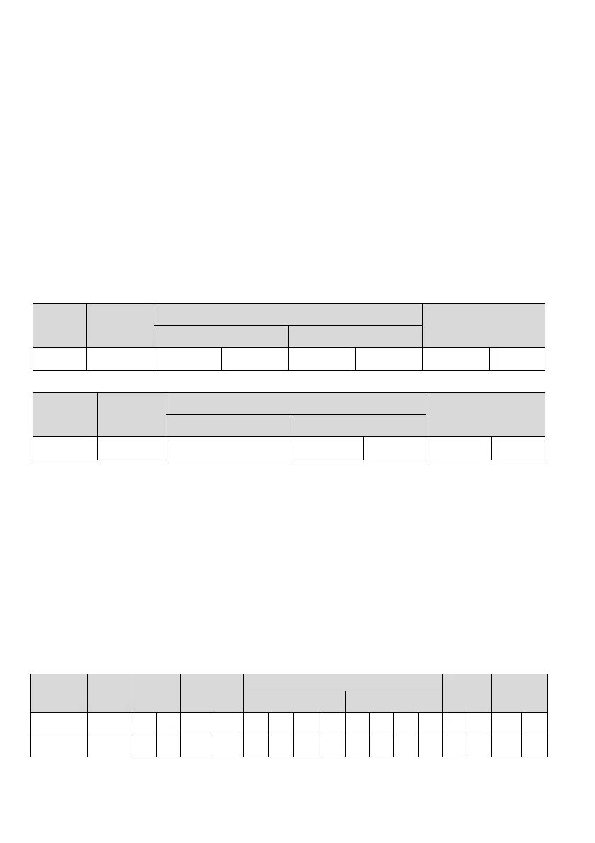
Request frame:
Slave
address
Command
code
Data
Check code
Register address Number of bytes read
0x05 0x03 0x01 0x01 0x00 0x01 0xD5 0xB2
Response frame:
Slave
address
Command
code
Data
Check code
Number of bytes
responded
Register content
0x05 0x03 0x02 0x13 0x88 0x44 0xD2
In the above table, the check code is the CRC verification value. Please refer to the following text for the
computing method of the CRC verification.
2. ASCII mode
In the ASCII mode, the frame header is “0x3A” and the frame trail is “0x0D, 0x0A” by default. The frame trail
can be set by the user as well. In this mode, except for the frame header and frame trail, all the other data
bytes are sent in the ASCII code mode. The 4 high bytes will be sent first, and then the 4 low bytes. In the
ASCII mode, the dada has 7 bytes. For “A” to “F”, their capital letter in the ASCII code will be used. The data
is verified by the LRC and the verification involves information from slave address to data. The checksum is
equivalent to the complement of the character sum of all the data in the check.
The following example shows writing 4000 (0xFA0) into the internal register 0201 (P02.05) of No.5 slave in the
ASCII mode.
Request frame:
Frame
head
Slave
address
Command
code
Data
Check
code
Frame trail
Register address Written content
Character : 0 5 0 6 0 2 0 1 0
FA043CRLF
ASCII 3A 30 31 30 36 30 32 30 31 30 46 41 30 34 33 0D 0A
 Loading...