242
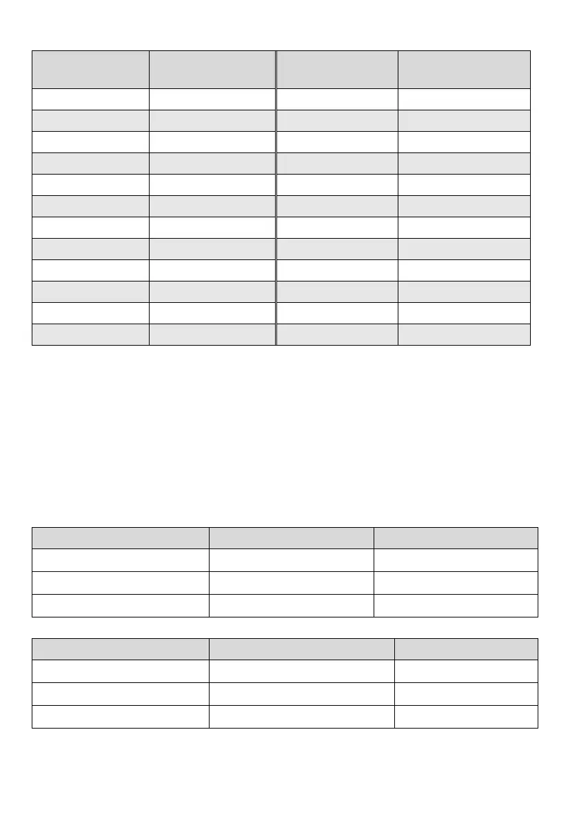
Drive parameter group
High byte of the address
mapped
Drive parameter group
High byte of the address
mapped
Group P00 0x00 Group P12 0x0C
Group P01 0x01 Group P13 0x0D
Group P02 0x02 Group P14 0x0E
Group P03 0x03 Group P15 0x0F
Group P04 0x04 Group P16 0x10
Group P05 0x05 Group P40 0x28
Group P06 0x06 Group P97 0x61
Group P07 0x07 Group P98 0x62
Group P08 0x08 Group P99 0x63
Group P09 0x09 Control parameter group 0x64
Group P10 0x0A Status parameter group 0x65
Group P11 0x0B …… ……
For example, the register address of the function code parameter P03.02 of the drive is 0x0302, and the
register address of the first control parameter (control word 1) is 0x6400.
As the format of the whole data frame has been detailed in the above text, the following text will focus on the
format and meanings of the “command code” and “data” of Modbus protocol. These two parts constitute the
Modbus application layer protocol data unit. Any reference to application layer protocol data unit to below
refers to such two parts. The following introduction to the frame format is based on RTU mode. For the ASCII
mode, the length of the application-layer protocol data unit shall be doubled.
1. Read the drive parameters
The application-layer protocol data units are as follows.
Request format:
Application-layer protocol data unit Data length (number of bytes) Value or range
Command code 1
0x03
Start register address 2
0x0000~0xFFFF
Number of registers 2
0x0001~0x000A
If the operation is successful, the response frame is as follows:
Application-layer protocol data unit Data length (number of bytes) Value or range
Command code 1 0x03
Number of bytes read 1 2 * Number of registers
Content read 2 * Number of registers Parameter value
 Loading...