216
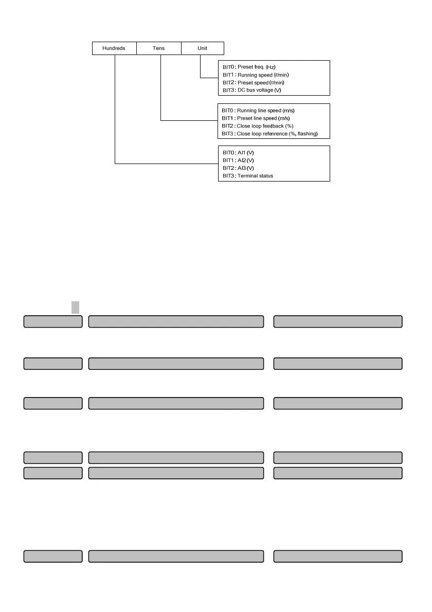
Fig. 6-78 Setting of LED display parameter selection when stop
This parameter defines the parameters that LED can display when the drive is in stop state.
When 0 is selected for the BIT bit, it indicates that the parameter is not displayed.
When 1 is selected for the BIT bit, it indicates that the parameter is displayed.
Note: When the rotating speed or the line speed is displayed, it can be directly changed by pressing ∧
or
∨ key (no need to switch into the frequency state).
When 0 is selected for all the P16.02 BIT bits, the set frequency will be displayed by default.
In the stop parameter display state, the parameters for display can be switched in turn by pressing the
shift key 》.
This function code is used for correcting the line speed proportion display error, and it has no influence on
the actual rotating speed.
This function code is used for correcting the rotating speed proportion display error, and it has no influence
on the actual rotating speed.
This function code is used for correcting the display error between the actual physical parameters
(voltage, flow, etc.) and the reference or feedback parameter (voltage, current) in the PID closed loop
control, and it has no influence on the PID closed loop adjustment.
P16.06 indicates the temperature of the inverter module. The over-temperature protection values of the
inverter modules of different types may be different.
P16.07 indicates the temperature of the rectifier. The temperature of the rectifier bridge below 18.5kW will
not be detected.
Temperature display range: 0~150
℃; precision: 5%.
Motor tem
erature measured
0~200℃
0
P16.08
Rectifier module tem
erature
0.0~150.0℃
0.0
P16.07
Inverte
module tem
erature
0.0~150.0℃
0.0
P16.06
Close loo
dis
la
coefficient 0.1~999.9%
100.0%
P16.05
Rotatin
s
eed dis
la
coefficient 0.1~999.9%
100.0%
P16.04
Line s
eed coefficient 0.1~999.9%
1.0%
P16.03
 Loading...