151
The process closed loop output is used as the torque limit reference. Please refer to the function code
descriptions in Group P14 for the settings of the process closed loop.
Fig. 6-23 Torque control diagram
Note
The torque limit value shall be a positive value. If it is set to be a negative value, the auto limit value will be 0.
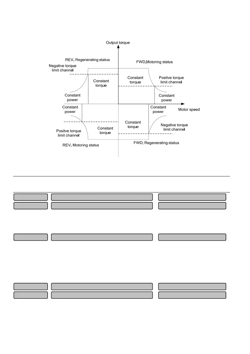
When P05.13 or P05.14 is selected to be 0, P05.15 and P05.16 are used to limit the maximum output
torque of the drive. The limit value is the percentage of the rated output torque of the motor. When large
negative torque is required, please adopt additionally the dynamic braking method.
0: Zero servo is disabled
1: Zero servo is always enabled
2: Zero servo is enabled under conditions (terminal enabled)
“Zero servo is enabled under conditions” means “zero servo enabled” can be realized through NO. 54
function of terminal Xi.
Upon closed loop vector control, when the motor speed is less than the rotating speed corresponding to
the zero servo initial frequency P05.19, if the zero servo is enabled to be always enabled or the
conditions are enabled and the terminal is enabled, it enters into the zero servo locking status. At this
time, the position of the motor in stop status will be maintained. The zero servo initial frequency is the
Zero servo initial frequency
0.00~10.00Hz
0.30Hz
P05.19
Zero servo gain
0~6.000
1.000
P05.18
Zero-servo function selection
0~2
0
P05.17
Braking torque limit value
0.0~300.0%
180.0%
P05.16
Electric torque limit value
0.0~300.0%
180.0%
P05.15
 Loading...