221
0: The drive generates an alarm and continues operating when the overload detection is enabled, and the
operation panel will display AL.oL1 or AL.oL2 according to the setting of the hundreds place.
1: The drive will activate protection action and coast to stop when the overload detection is enabled, and
the operation panel will display Er.oL1 or Er.oL2 according to the setting of the hundreds place.
Thousands place: Overload detection level selection
0: The detection level relative to the motor rated current (Alarm code AL.oL2 and fault code Er.oL2)
1: The detection level relative to the drive rated current (Alarm code AL.oL1 and fault code Er.oL1)
This function code defines the current threshold for the overload pre-alarm action. The setting value is the
percentage relative to the rated current (refer to the thousands place of P97.03).
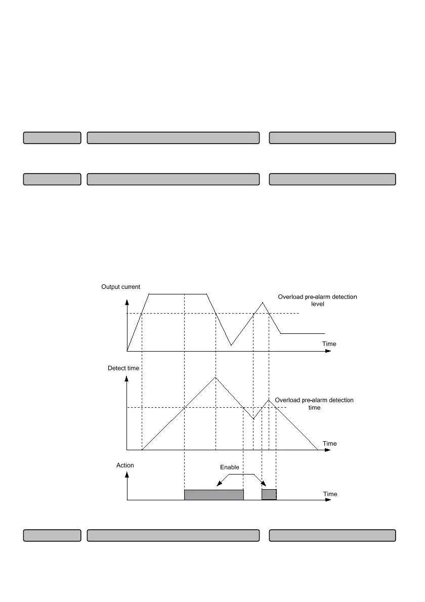
This function code defines the output overload pre-alarm signal after the time that the drive output current
is greater than the overload detection level (P97.04) exceeds the setting time.
When the drive output current is higher than the overload detection level (P97.04), the pre-alarm
detection timing will be gradually increased. When the drive output current is lower than the overload
detection level, the pre-alarm detection timing will be gradually decreased. When the overload pre-alarm
status is enabled, it means that the drive overload detection timing time exceeds the overload pre-alarm
detection time. Schematic diagram for the overload pre-alarm detection function is shown as follows:
Fig. 6-83 Schematic diagram for the overload pre-alarm detection function
Motor ove
-tem
erature
rotection
oint 0~10.00V
10.00
P97.06
Overload
re-alarm detection time 0.0~60.0s
5.0s
P97.05
Overload
re-alarm detection level 20.0~200.0%
130.0%
P97.04
 Loading...