256
and 32-bit mode are identified through the “start register address” of the request frame. If the highest byte of
the address is 0, the reading/writing shall be done in the 16-bit mode, otherwise, they shall be done in the
32-bit mode. As shown in the following table.
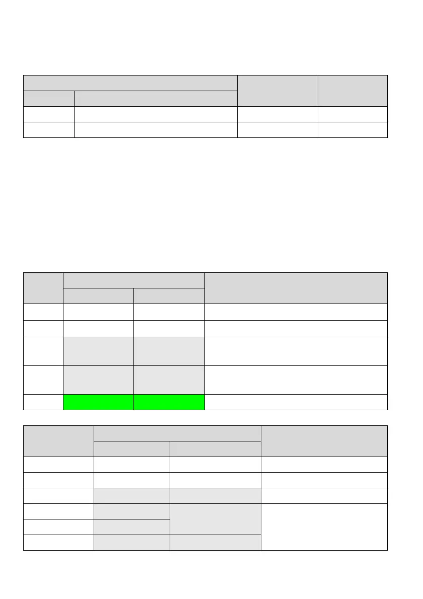
Start register address
Access mode Remarks
BIT15 BIT14~BIT0
0 Actual address of the start parameter 16-bit
1 Actual address of the start parameter 32-bit
When accessing to the parameters in the 32-bit mode, as the unit of the register of the request frame is 16 bits
and each parameter of 32 bits needs two registers of 16 bits, the “number of registers” shall be set correctly.
The “number of registers” in the request frame shall be twice of that of the parameters to be accessed to,
otherwise, it will return to the abnormal response frame.
1. Reading operation
The 16-bit access mode is as described above.
For the 32-bit access mode, the unit of the data returned is 32 bits.
As shown in the following table, reading 4 continuous function codes with P01.01 as the start address (the
slave address is 5).
Request frame:
Bytes
Value
Description
16-bit mode 32-bit mode
0
0x05 0x05
Slave address
1
0x03 0x03
Command code
2~3
0x0101 0x8101
Start address (in the 32-bit mode, the highest byte of the
start address is 1)
4~5
0x0004 0x0008
Number of registers (in the 32-bit mode, the number of
registers is twice of that of parameters)
6~7 Check code Check code CRC verification
If the operation is successful, the response frame is as follows:
Bytes
Value
Description
16-bit mode 32-bit mode
0 0x05 0x05 Slave address
1 0x03 0x03 Command code
2 0x08 0x10 Number of bytes read
3~4 Value P01.01
Value P01.01
Content read:
16-bit mode: 8 bytes in total
32-bit mode: 16 bytes in total
5~6 Value P01.02
7~8 Value P01.03 Value P01.02
 Loading...