269
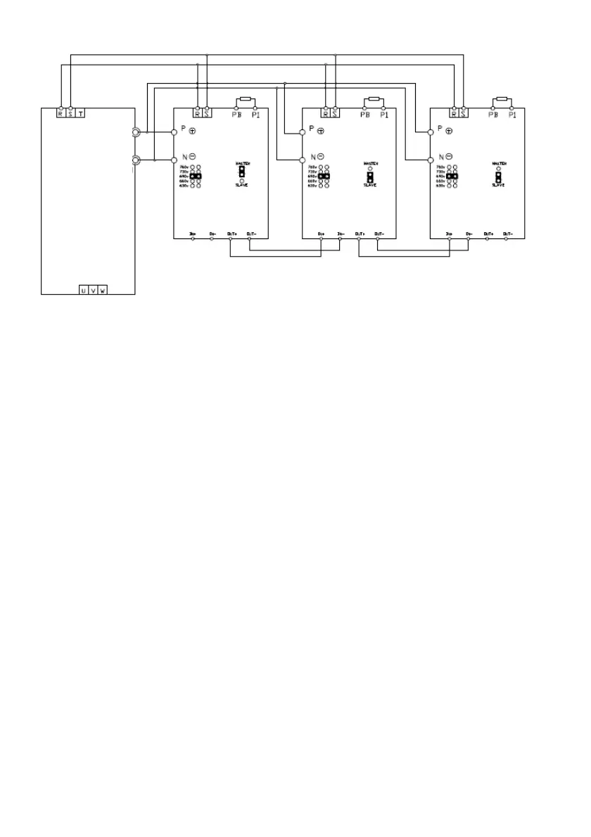
Attached Fig.2-3 Connection diagram of the drive and braking component
4) Functions of brake unit
·Brake unit action voltage adjustment;
·Heatsink overheat protection;
·Fault display and fault relay output indication;
·The external brake unit has tripping function after IGBT short circuit, effectively preventing hidden
fire dangers incurred by long-time overload operation of the resistor.
The connecting wire between the brake units and drive, and between the brake units and brake resistors shall
be bunched and the length shall be within 5m. If it is longer than 5m, twisted pair wire shall be adopted. The
maximum wire length is 10m.
+DC
-DC
380VAC Input
Brake Resistor
Drive
Brake Resistor Brake Resistor
 Loading...