33
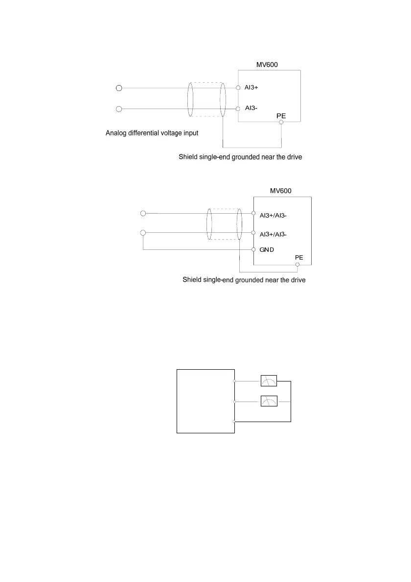
2) When the AI3+ and AI3- terminals receive the analog voltage differential input or analog voltage single-end
input, the wiring mode is as shown in Fig. 3-7 and Fig. 3-8.
10V~10V-
Fig. 3-7 Wiring diagram for AI3+ and AI3- terminals to receive differential voltage input
10V~10V-
Fig. 3-8 Wiring diagram for AI3+ and AI3- terminals to receive single-end voltage input
Analog output terminal wiring
The external analog meter of the analog output terminals AO1 and AO2 can indicate various parameters. The
analog output of the voltage/current is selected via the jumper, and the output range of the analog
voltage/current is selected in the function code P10.22. The terminal wiring mode is
as shown in Fig. 3-9.
Fig. 3-9 Analog output terminal wiring
O1
O2
GND
nalog mete
MV600
0: 0~10V(or 0~20mA)
1: 2~10V(or 4~20mA)
0: 0~10V(or 0~20mA)
1: 2~10V(or 4~20mA)
Unit place of P10.22: AO1 select
Tens place of P10.22: AO2 select
 Loading...