ENGINE MECHANICAL SERVICE MANUAL NUMBER 22
Page 3A-64 90-860074--1 FEBRUARY 2002
4. Using a screwdriver install two Cylinder Head Guide Pins (91-801333501) into 12 mm
bolt holes in cylinder block at cylinder number 1 location.
5. On D2.8L D-Tronic Engines: Using a screwdriver install two Cylinder Head Guide Pins
into 12 mm bolt holes in gasket and cylinder block at cylinder number 4 location. These
pins will keep the gasket aligned.
6. On D4.2L D-Tronic Engines: Using a screwdriver install two Cylinder Head Guide Pins
91-801333501, into 12mm bolt holes in gasket and cylinder block at cylinder number 3
location. These pins will keep the gasket aligned.
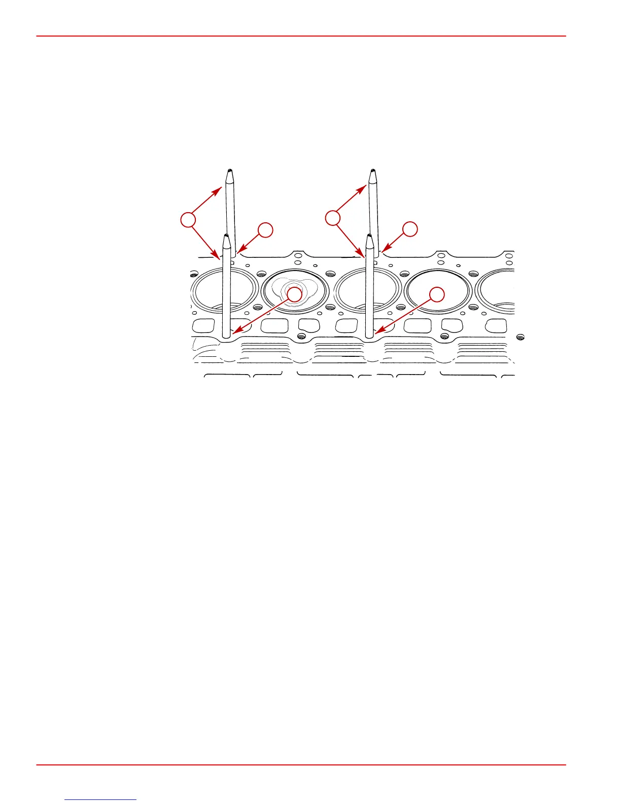
78143
a
a
b
b
a
a
D4.2L D-Tronic Guide Pin Locations Shown (D2.8L Similar)
a-Guide Pin, Bolt Hole Locations (Two at each cylinder)
b-Guide Pins Installed
7. Beginning with cylinder number 1, install a cylinder head over the guide pins.
8. ONE AT A TIME, remove Guide Pins and install the oiled 12mm cylinder head bolts with
washers HAND tight. Do NOT disturb head placement.
9. Using a screwdriver install two Cylinder Head Guide Pins, into 12 mm bolt holes in
cylinder block for the next cylinder in numerical order.
10. On D2.8L D-Tronic Engines: Repeat for each cylinder head and corresponding
cylinder 2 through 4.
11. On D4.2L D-Tronic Engines: Repeat for each cylinder head and corresponding
cylinder 2 through 3.
12. On D4.2L D-Tronic Engines: Repeat the installation process for the gasket and each
cylinder head corresponding to cylinder 4 through 6.

 Loading...


