EDI DIAGNOSIS
SERVICE MANUAL NUMBER 22
90-860074--1 FEBRUARY 2002 Page 5E-15
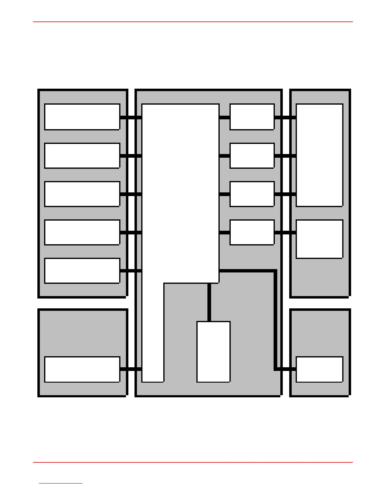
ECM Input and Sensor Diagram
The following shows the sensors, switches, other inputs and outputs used by the ECM to
control its various systems. Although we will not cover them all in great detail, there will be
a brief description of each.
Sensors ECM Actuators
Number 1 Cylinder
Injected fuel
Fuel Injector (Needle-
motion sensor)
Injected fuel
quantity
Electronically
controlled
fuel injection
Temperature sensors
(water, air, fuel)
Engine
shut off
fuel injection
pump (Fuel
Quantity and
Timing)
Micro-
Sensor for control-
collar position
processors
Start of
injection
Engine speed sensor
Starting
control
Glow control
unit
MAP sensor
Setpoint
generators
Diagno-
sis
Maps
TP sensor
Diagnostic
display

 Loading...


