EDI DIAGNOSIS
SERVICE MANUAL NUMBER 22
90-860074--1 FEBRUARY 2002 Page 5E-27
TEST DESCRIPTION
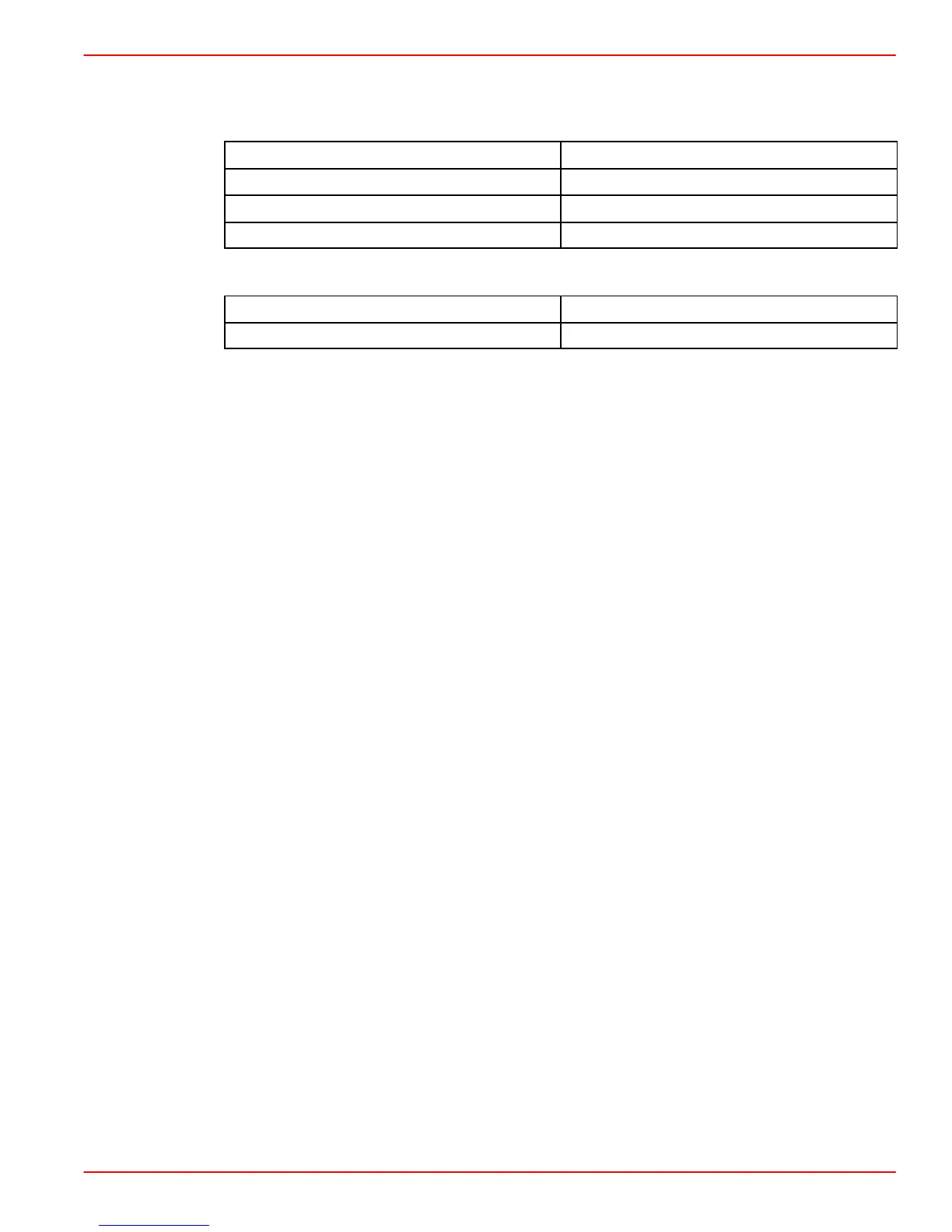
Verify continuity between the following:
ECM 68 PIN CONNECTOR
3 TERMINAL CONNECTOR
8 2
21 1 and 3 (3 is shield wire)
21 3 (shield wire)
Verify the resistance between terminals 1 and 2 of the sensor:
RESISTANCE (Ohm)
MAXIMUM MEASUREMENT
1000 1000 ohm
DIAGNOSTIC HELP:
Verify the following:
• Open or short in the CKT Pin 8 or CKT Pin 21.
• Bent pin at the 3 terminal connector or ECM.
• Sensor mounting is improper.
• Defective rpm sensor or ECM.
RPM Sensor failure influences engine performance as follows:
• The engine will not start If the engine speed sensor fails during starting procedures.
The MIL (Malfunction Indicator Lamp) IS NOT illuminated.
• The engine immediately shuts OFF if the engine speed sensor fails with the engine
operating. The MIL IS illuminated.

 Loading...


