Section 5 - Maintenance
Page 110 90-879172181 eng FEBRUARY 2011
Tube Ref No. Description Where Used Part No.
94
Anti-Corrosion Grease Propeller shafts 92-802867Q 1
34
Special Lubricant 101 Propeller shaft 92-802865Q02
95
2-4-C Marine Lubricant
with Teflon
Propeller shaft 92-802859A 1
3. Install the propellers. Refer to Propellers.
Driveshaft Connection Torque
1. Remove the engine and transmission end driveshaft shields, if not already. Refer to Driveshaft U-Joints.
2. Tighten the driveshaft flange to the transmission input flange bolts and nuts as specified.
NOTE: Some models have larger diameter transmission input and driveshaft flanges (175 mm [6.88 in.]) and use eight bolts
and nuts. Ensure the bolts and nuts are at least Grade 8 fasteners before tightening.
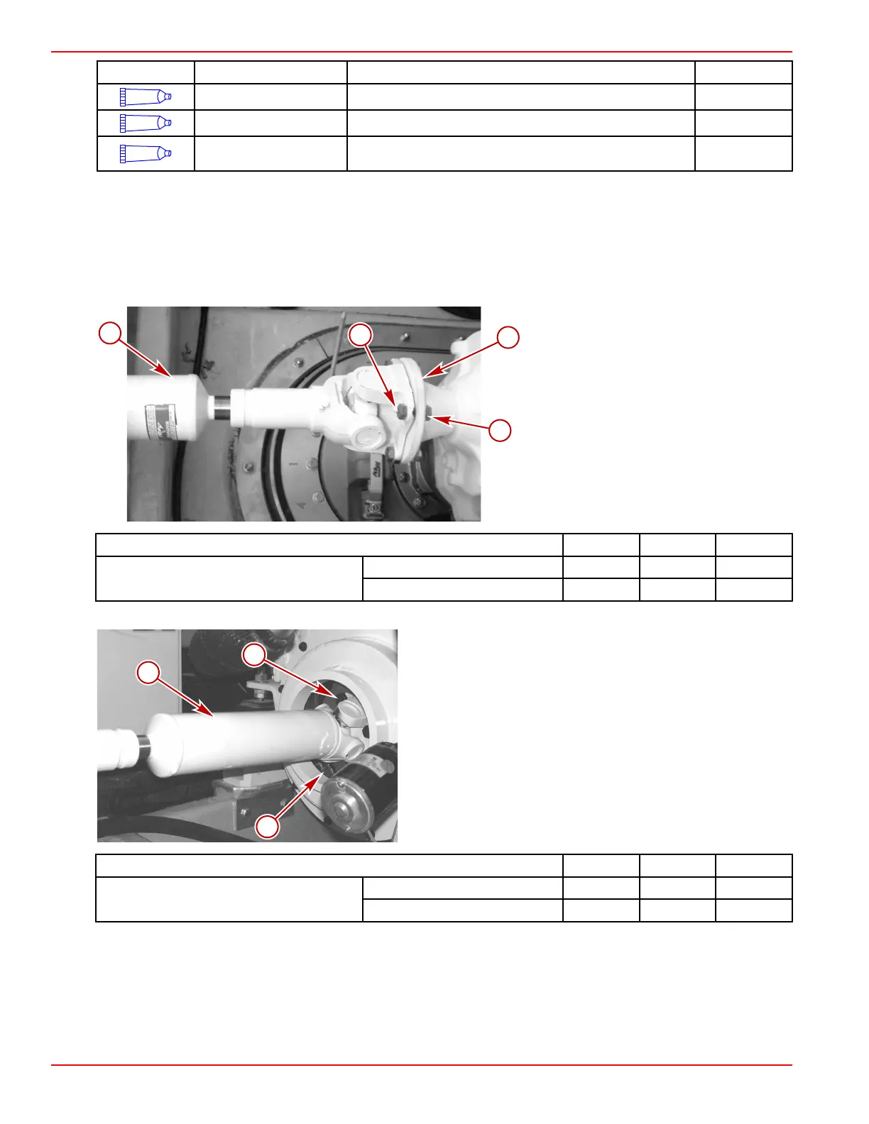
Typical four-bolt flange shown, eight-bolt
similar
a - Locknut
b - Transmission input shaft flange
c - Bolt, four total (QSB, QSC), eight total
(QSM), per flange
d - Driveshaft
Description Nm lb. in. lb. ft.
Transmission input shaft flange locknut
Four‑bolt flange 149 – 110
Eight‑bolt flange 61 – 45
3. Tighten the driveshaft input flange screws to the engine coupler as specified.
Typical four-screw flange shown, eight-screw similar
a - Screw, four total (QSB, QSC), eight total (QSM), per
flange
b - Engine coupler flange
c - Driveshaft
Description Nm lb. in. lb. ft.
Engine coupler‑to‑drive shaft flange screw
Four‑screw flange 149 – 110
Eight‑screw flange 61 – 45
 Loading...