Section 2 - Getting to Know Your Power Package
90-879172181 eng FEBRUARY 2011 Page 17
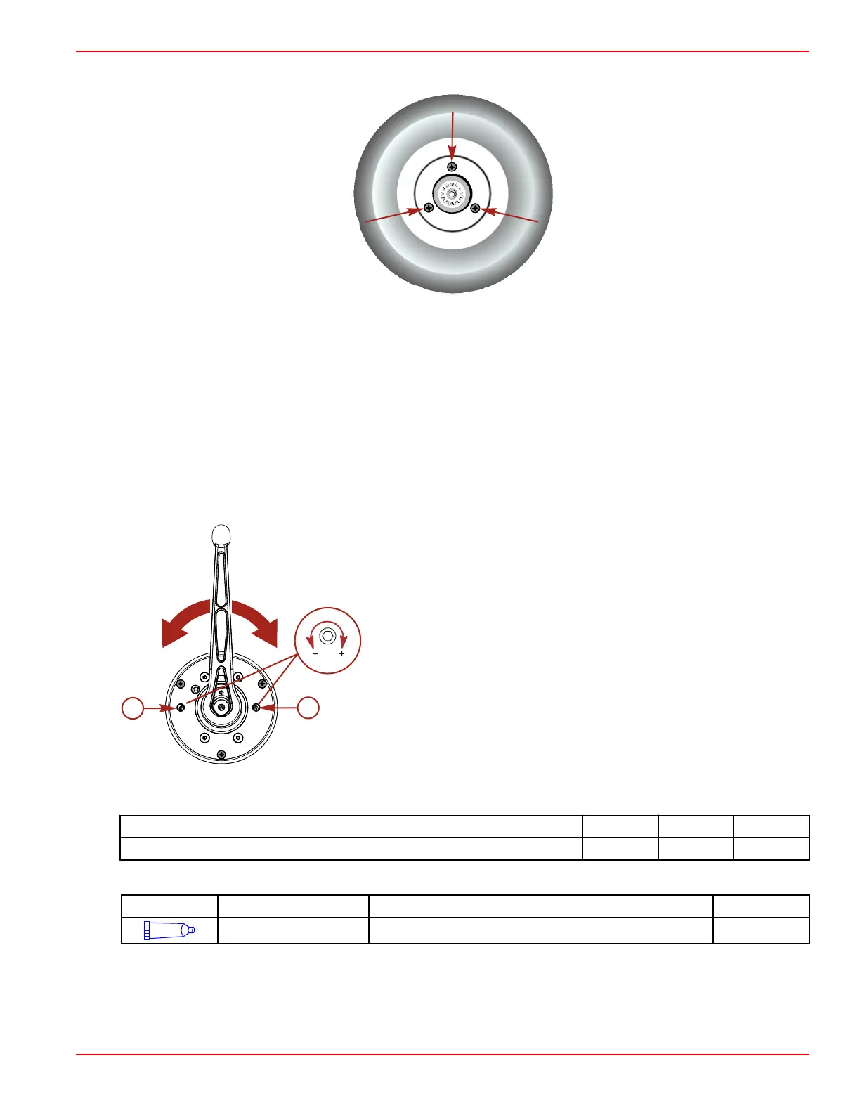
4. Remove the three M5 screws securing the side cover.
Location of side cover screws
5. Remove the side cover.
6. For adjustment, temporarily install the handle, washer and screw. Finger‑tighten the screw.
7. To adjust the ERC handle detent tension:
a. Turn the adjustment screw clockwise to increase tension on the control handle and counter‑clockwise to decrease
tension.
b. Adjust to the desired tension.
8. To adjust ERC handle tension:
a. Turn the adjustment screw clockwise to increase tension on the control handle and counter‑clockwise to decrease
tension.
b. Adjust to the desired tension.
Side cover removed
a - Detent tension adjustment screw
b - Handle tension adjustment screw
9. Remove the screw, washer, and handle when the adjustments are complete.
10. Install the side cover. Secure the cover with the three M5 x 10 mm long screws. Tighten the screws to specification.
Description
Nm lb‑in. lb‑ft
Side cover screws 3.4 30 –
11. Apply adhesive to the threads of the handle screw.
Tube Ref No.
Description Where Used Part No.
7
Loctite 271 Threadlocker Threads of handle screw 92-809819