4 Prepare Parts for Assembly
23
Meritor Maintenance Manual MM-15103 (Issued 07-17)
Figure 4.15
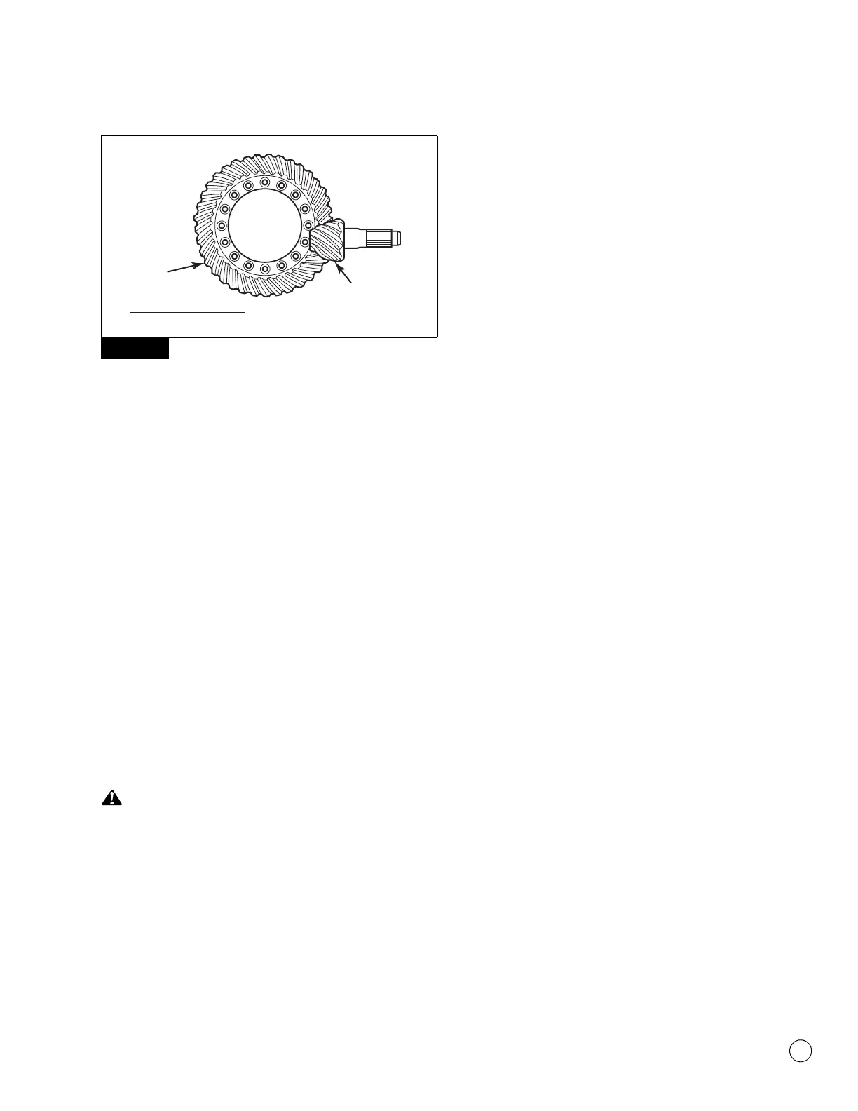
2. Count the number of pinion gear teeth. Figure 4.15.
3. Divide the number of ring gear teeth by the number of pinion
gear teeth to determine the actual gear set ratio for each axle.
Figure 4.15.
4. Calculate the percentage difference between the gear set
ratios. All ratios must match within one percent.
앫 If the actual gear set ratios are not within one percent
of each other: Refer to the vehicle manufacturer for further
information.
Inspection
Yoke
All current Meritor axles feature helical splines at the yoke interface.
This feature provides a tight fit between the yoke and input shaft,
output shaft and pinion shaft. For the axle to operate correctly, the
input shaft, output shaft and pinion shaft must fit tightly to the
corresponding yoke.
Check for Yoke Wear
Park the vehicle on a level surface. Block the wheels to
prevent the vehicle from moving. Support the vehicle with
safety stands. Do not work under a vehicle supported only by
jacks. Jacks can slip and fall over. Serious personal injury and
damage to components can result.
1. Park the vehicle on a level surface. Block the wheels to prevent
the vehicle from moving.
2. Use a jack to raise the vehicle so that the wheels to be serviced
are off the ground. Support the vehicle with safety stands.
3. Remove the driveline.
4. Remove the pinion shaft nut.
5. Attempt to remove the yoke by hand.
앫 If you can remove the yoke by hand: The yoke is worn.
Replace the yoke.
6. Use a correct yoke puller tool to remove the yoke.
Check for a Tight-Fit Condition
NOTE: You can check for a tight-fit condition when you install any
serviceable yoke.
1. Attempt to install the yoke by hand.
앫 If the yoke bottoms out against the adjacent bearing:
Replace the yoke.
2. Use a correct yoke installation tool to install the yoke.
3. As you install the yoke, you should detect resistance between
the yoke and shaft.
앫 If you do not detect resistance between the yoke and
shaft: Replace the yoke.
4. Install and tighten the pinion shaft nut to the correct torque.
Refer to Section 7.
5. Install the driveline.
6. Remove the safety stands.
7. Lower the vehicle.
Figure 4.15
4012516a
RING GEAR TEETH
PINION GEAR TEETH
=
ACTUAL
GEAR SET RATIO
PINION
GEAR TEETH
RING
GEAR
TEETH