5 Assembly and Installation
43
Meritor Maintenance Manual MM-15103 (Issued 07-17)
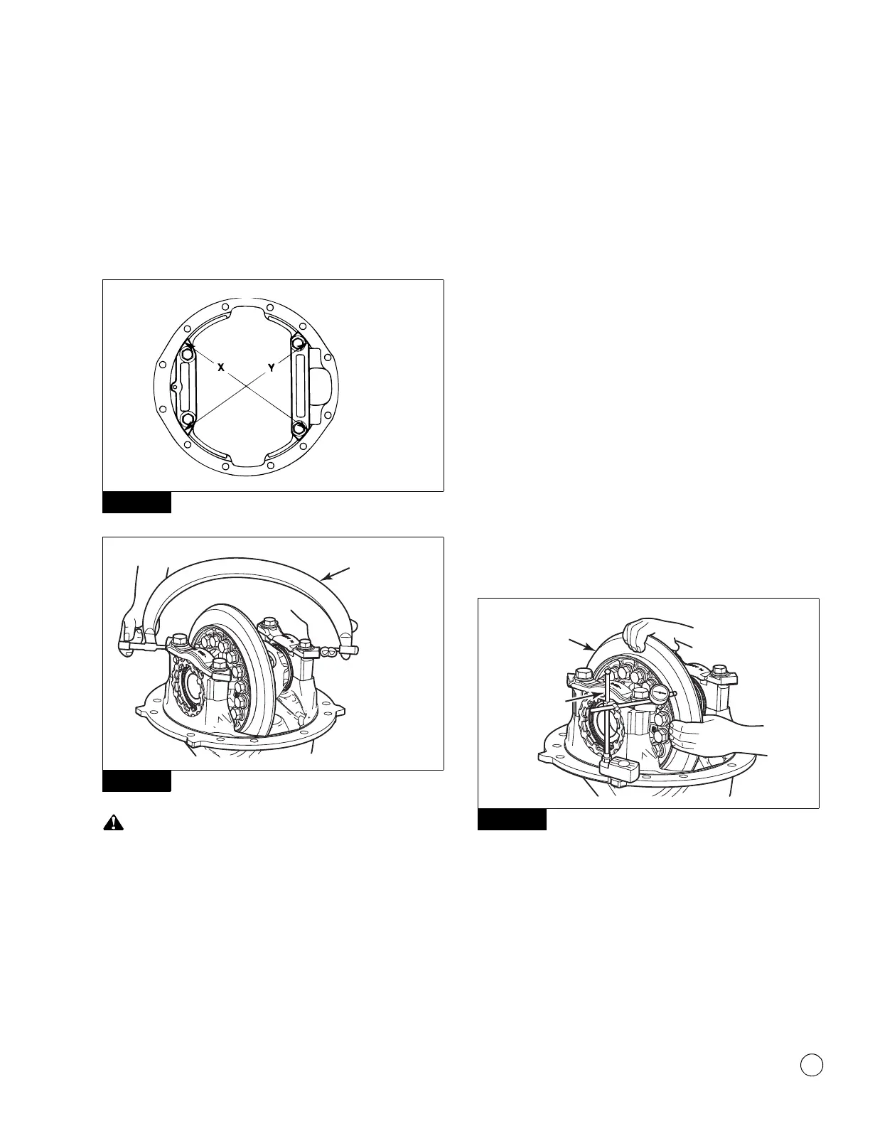
Large Micrometer Method
1. Hand-tighten the adjusting rings against the differential
bearings.
2. Use a large 13-14-inch micrometer to measure distance X and
Y between the opposite surfaces of the bearing caps. Record
the measurement. Figure 5.63 and Figure 5.64.
Figure 5.63
Figure 5.64
When turning the adjusting rings, always use a tool that
engages two or more opposite notches in the ring. An
adjusting ring tool can be used for this purpose. If the tool does
not correctly fit into the notches, damage to the lugs will occur.
3. Use an adjusting ring tool to tighten each bearing adjusting ring
one notch. Figure 5.59.
4. Measure distance X and Y again. Compare the measurements
with the distances X and Y measured in Step 2. The difference
between the two distances is the amount the bearing caps
have expanded. Refer to Table D.
Table D: Example
5. If the difference is at or between 0.002-0.009-inch
(0.05-0.23 mm): Continue by checking the runout.
If the difference is not within 0.002-0.009-inch
(0.05-0.23 mm): Repeat as needed.
Ring Gear Runout
1. Attach a dial indicator onto the carrier mounting flange.
Figure 5.65.
Figure 5.65
2. Adjust the dial indicator so that the plunger or pointer is against
the back surface of the ring gear. Figure 5.65. Set the dial
indicator to ZERO.
3. Rotate the differential and ring gear. Read the dial indicator.
The ring gear runout must not exceed 0.008-inch (0.200 mm).
Figure 5.63
Figure 5.64
Distances X and Y BEFORE
tightening the adjusting rings
= 13.927-inches (353.75 mm)
Distances X and Y AFTER
tightening the adjusting rings
= 13.932-inches (353.87 mm)
13.932-inches –
13.927-inches
= 0.005-inch difference
353.87 mm – 353.75 mm = 0.12 mm difference
Figure 5.65
4012314a
DIAL
INDICATOR
Rotate ring
gear.