5 Assembly and Installation
41
Meritor Maintenance Manual MM-15103 (Issued 07-17)
Correctly install the bearing caps into their original locations
on the carrier. Do not force the bearing caps into position,
which can damage the carrier. If the bearing caps are not
installed correctly, the bores and threads in the cap will not
match the carrier. Damage to the adjusting rings by
cross-threading can result.
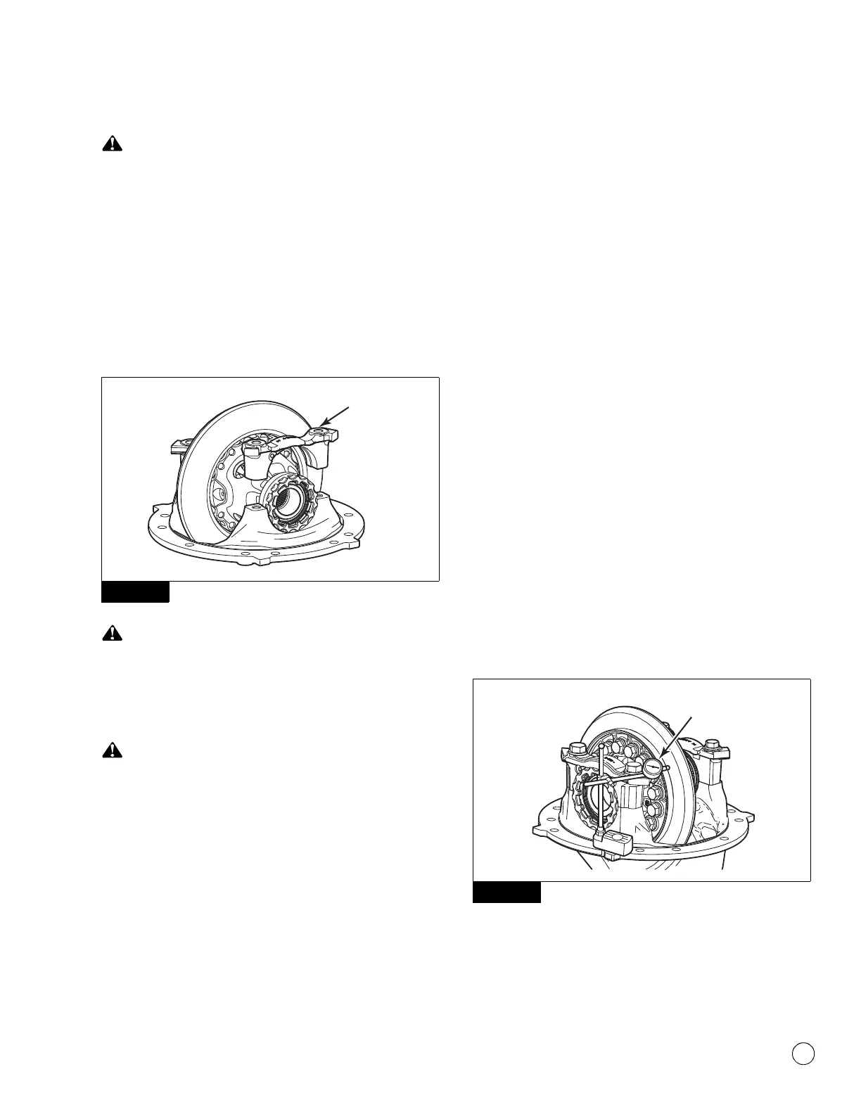
8. Install the bearing caps over the bearings and adjusting rings in
the correct location. Check the shape of the mounting face on
the carrier legs to ensure the bearing caps are installed in the
correct position. Figure 5.57.
Figure 5.57
Use a brass or synthetic mallet for assembly and disassembly
procedures. Do not hit steel parts with a steel hammer. Pieces
of a part can break off. Serious personal injury and damage to
components can result.
Correctly install the bearing caps into their original locations
on the carrier. Do not force the bearing caps into position,
which can damage the carrier. If the bearing caps are not
installed correctly, the bores and threads in the cap will not
match the carrier. Damage to the adjusting rings by
cross-threading can result.
9. Use a light leather, plastic or rubber mallet to seat each bearing
cap. The caps must fit easily against the bearings, adjusting
rings and carrier. Do not force the bearing caps into position.
앫 If the bearing caps do not correctly fit into position:
Check that the bearing caps are installed in the correct
position. Remove the caps and reinstall them.
10. Hand-tighten the adjusting rings against the bearing cups to
position the ring gear to the pinion with 0.012-inch (0.3 mm)
backlash.
11. Install the capscrews and washers that secure the bearing
caps to the carrier. Tighten the capscrews to 25 lb-ft (34 N폷m).
This is an initial tightening torque and will be increased later in
the procedure.
@
Do not install the capscrews and washers that secure the
bearing adjusting rings in position. After the ring gear is
installed, you must adjust the backlash of the ring gear, inspect
the tooth contact patterns, then adjust the preload of the
differential bearings before the capscrews and washers are
installed.
Adjustment
Differential Bearings Preload
Use either the dial indicator or the large micrometer method to
inspect and adjust the main differential side bearings preload.
NOTE: The capscrews and washers for the adjusting rings are
installed after the tooth contact pattern is rechecked.
Dial Indicator Method
1. Attach a dial indicator onto the carrier mounting flange so that
the plunger or the pointer is against the back surface of the
ring gear. Figure 5.58.
Figure 5.58
Figure 5.57
Figure 5.58
4011994a
DIAL
INDICATOR