5 Assembly and Installation
40
Meritor Maintenance Manual MM-15103 (Issued 07-17)
앫 To increase preload: Install a thinner bearing variable
spacer.
앫 To decrease preload: Install a thicker bearing variable
spacer.
8. Once the desired preload is obtained, remove the used yoke.
Install the seal and the service yoke. Refer to the procedures in
this section.
Replace the Variable Spacer to Adjust Pinion
Bearing Preload
NOTE: Do not grind spacers by hand. The surfaces must be parallel
within 0.0001-inch (0.0020 mm). You must use the correct
spacers.
If you must adjust preload, use the following procedure to replace
the variable spacer with one of a different thickness.
1. Install a yoke or flange bar to prevent the drive pinion assembly
from rotating. Remove the nut and the washer from the shaft of
the drive pinion.
2. Press the drive pinion out of the bearing cone. Remove the
outer bearing cone from the differential carrier.
3. Reinstall the drive pinion assembly using the correct size
variable spacer.
4. Recheck the drive pinion bearing preload using the procedure
in this section.
“Final” Installation of the Main Differential
Case and Ring Gear Assembly Into the
Carrier
1. Rotate the carrier in the repair stand until the back surface of
the ring gear is toward the TOP.
2. Clean and dry the bearing cups and bores of the carrier legs
and bearing caps.
3. Apply axle lubricant to the bearing cones and inside surface of
the bearing cups.
NOTE: Meritor specification 2297-P-3994 adhesive will dry in
approximately two hours. You must complete the procedure within
two hours from the time you apply the adhesive. If two hours have
passed since application, clean the adhesive from the parts and
apply new adhesive.
4. Apply Meritor specification 2297-P-3994, Loctite
680
adhesive or equivalent 360 degrees around the outside
diameter of the bearing cups. The adhesive must not contact
the adjusting ring threads. Refer to Section 4.
5. Install the bearing cups over the bearing cones in the case
halves. Figure 5.55.
Figure 5.55
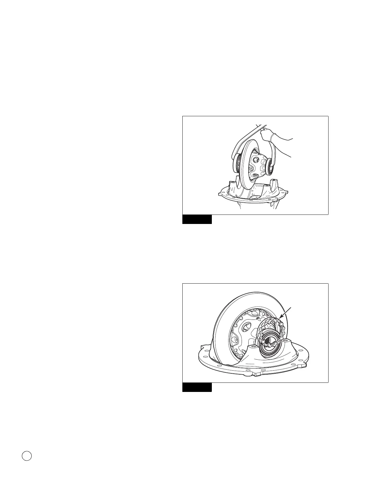
6. Safely lift the differential and ring gear assembly and install it
into the carrier. The bearing cups must be flat against the
bores between the carrier legs. Figure 5.55.
7. Install the bearing adjusting rings between the carrier legs.
Figure 5.56.
Figure 5.56
Figure 5.55
Figure 5.56
4011964a
4012324a
ADJUSTING
RING