5 Assembly and Installation
44
Meritor Maintenance Manual MM-15103 (Issued 07-17)
앫 If the ring gear runout is within the specification: Set
the backlash and contact patterns to the settings
determined in the “Check Gear Set Tooth Contact Patterns”
procedure in this section.
앫 If the ring gear runout exceeds the specification:
Remove the differential and ring gear assembly from the
carrier.
A. Inspect the differential parts, including the carrier, for
wear and damage. Repair or replace parts as necessary.
B. Install the main differential case and ring gear assembly
into the carrier. Refer to the procedure in this section.
C. Repeat the procedure for preload adjustment of the
differential side bearings.
4. Once the adjustments are complete, tighten the bearing cap
capscrews as follows.
앫 Flange side bearing cap capscrews: Tighten to
320-400 lb-ft (430-540 N폷m).
@
앫 Plain half side bearing cap capscrews: Tighten to
200-258 lb-ft (270-350 N폷m).
@
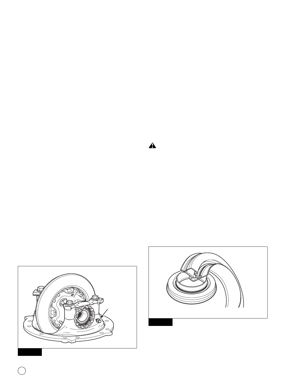
5. Once all adjustments are complete, install the capscrews and
washers that hold the two bearing adjusting rings in position.
Use the following procedure.
A. On each bearing cap, install two capscrews and washers
in the holes on the bearing cap so that the capscrews are
between the lugs of the adjusting ring. New capscrews
include a locking patch, which can only be used once. If
you are installing used capscrews, apply Loctite
242
threadlocker to the capscrew threads before installing the
capscrews. Figure 5.66.
Figure 5.66
B. Tighten the adjusting ring capscrews to 22-30 lb-ft
(30-40 N폷m).
@
Installation
Unitized Pinion Seal and Yoke
1. Remove the old seal. Do not damage the seal area of the
carrier. Do not touch or allow dirt or grease to contaminate the
sealing surface areas or the adjacent bearings.
2. Inspect the seal area of the carrier for damage that could
cause lubricant leaks after you install the seal. Use emery
paper or an equivalent product to remove scratches, nicks or
burrs only.
Inspect the axle breather for contaminants, such as dirt,
lubrication or debris, which can cause pressure to build inside
the axle. Damage to the seal and premature seal lip wear can
result. Remove the axle breather. Use a safe cleaning solvent
to clean the inside and outside of the breather.
3. Inspect the axle breather for contaminants, such as dirt,
lubrication or debris.
앫 If you find contaminants in the axle breather: Remove
the axle breather. Use a safe cleaning solvent to clean the
inside and outside of the breather.
4. Remove the replacement unitized seal from the package.
Figure 5.67.
Figure 5.67
Figure 5.66
4011961a
CAPSCREW
AND
WASHER
Figure 5.67
4005523a