5 Assembly and Installation
38
Meritor Maintenance Manual MM-15103 (Issued 07-17)
Figure 5.50
6. If the backlash and contact patterns are correct, remove the
leg cap capscrews. Use an appropriate lifting device to remove
the ring gear.
Installation
“Final” Installation of the Drive Pinion and
Bearing Preload Adjustment
Use the shim pack and backlash established by the “dry fit”
procedure for final assembly.
The preload of the bearings on the drive pinion is controlled by a
variable spacer behind the outer bearing cone.
Adjust the preload by changing the size of the spacer.
앫 To decrease the preload: Use a thicker spacer.
앫 To increase the preload: Use a thinner spacer.
If the depth of the drive pinion is changed, the thickness of the
spacer must also be changed the same amount. Refer to the
following examples.
앫 If a 0.003-inch (0.076 mm) shim is ADDED to the shim pack
to INCREASE the depth of the drive pinion: A 0.003-inch
(0.076 mm) larger spacer must be installed to keep the preload
on the bearings.
앫 If a 0.003-inch (0.076-mm) shim is REMOVED from the shim
pack to DECREASE the depth of the drive pinion: A
0.003-inch (0.076 mm) smaller spacer must be installed to keep
the preload on the bearings.
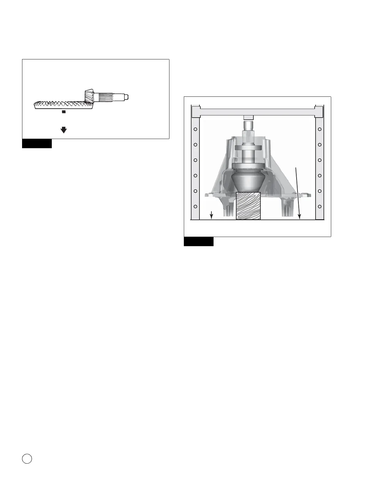
Install the Drive Pinion
1. Apply axle lubricant to the pinion bearing cups and cones.
2. Place the carrier into a press. Figure 5.51.
Figure 5.51
3. Install the pinion shaft assembly into the carrier. Seat the inner
bearing cone fully against the inner bearing cup. Figure 5.51.
4. Support the pinion shaft with blocks of wood so that the inner
bearing cone remains in contact with the inner bearing cup.
Figure 5.51.
5. Install the fixed spacer onto the pinion stem.
6. Install the variable spacer onto the pinion stem. If the depth of
the drive pinion has increased or decreased, select a variable
spacer with the same change in thickness. Figure 5.52.
Figure 5.50
Increase.
backlash.
Move pattern toward
toe, tighten adjusting
ring this side.
Loosen adjusting
ring this side.
1002805b
Figure 5.51
4011978c
Carrier should
not touch
the surface
of the press.
BLOCK OF WOOD
SUPPORTING PINION
PRESS
SURFACE