5 Assembly and Installation
37
Meritor Maintenance Manual MM-15103 (Issued 07-17)
Figure 5.46
4. Change the thickness of the shim pack under the inner pinion
bearing cup to move the contact patterns between the top and
root of the gear teeth. Use the following procedure.
NOTE: If the shim pack is changed, the bearing preload must
be rechecked.
A. Remove the drive pinion, inner bearing cup and shims
from the carrier. Refer to Section 3.
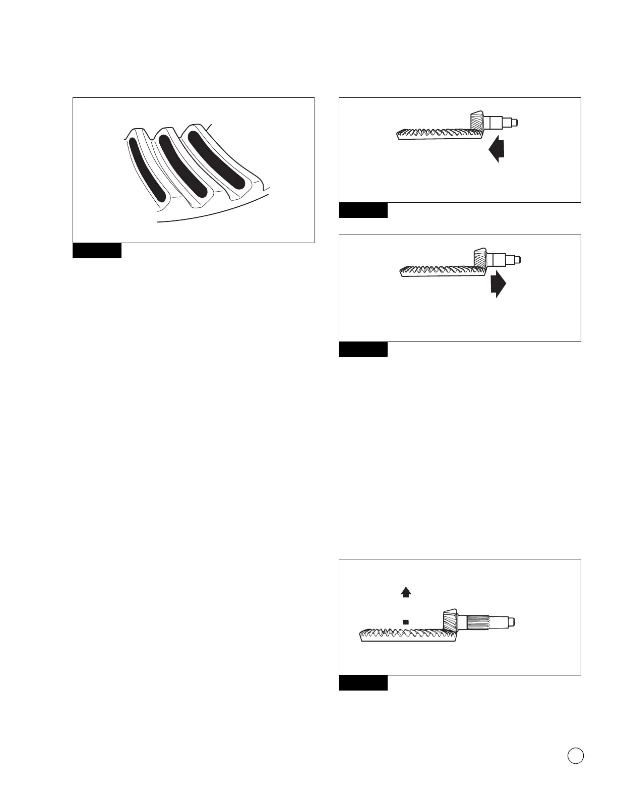
앫 To correct a high-contact pattern: Increase the
thickness of the shim pack under the inner bearing
cup, which moves the drive pinion TOWARD the ring
gear. This also moves the convex contact pattern
towards the heel and concave pattern towards the toe.
Figure 5.38 and Figure 5.47.
앫 To correct a low-contact pattern: Decrease the
thickness of shim pack under the inner bearing cup,
which moves the drive pinion AWAY from the ring gear.
This also moves the convex contact pattern towards
the toe and concave pattern towards the heel.
Figure 5.48.
B. Install the drive pinion, inner bearing cup and shims into
the carrier. The pinion cone number can be either 100ths
of a millimeter or 1,000ths of an inch.
C. Repeat Step 1 through Step 4 until the contact patterns
are in the center between the top and bottom of the gear
teeth.
Figure 5.47
Figure 5.48
5. Adjust ring gear backlash within the correct specification to
move the contact patterns to the correct location in the length
of the gear teeth. Refer to Ring Gear Tooth Contact Pattern,
Backlash in this section.
A. Decrease the backlash to move the convex pattern toward
the toe and concave pattern toward the heel. Figure 5.49.
B. Increase the backlash to move the convex pattern toward
the heel and the concave pattern toward the toe.
Figure 5.50.
C. Repeat Step 1 through Step 3 and Step 5 until the contact
patterns are at the correct location in the length of the
gear teeth.
Figure 5.49
Figure 5.46
4008139a
SATISFACTORY PATTERN IN OPERATION
CONVEX
Figure 5.47
Figure 5.48
Figure 5.49
1003102f
Increase shim pack.
1003101f
Decrease shim pack.
Decrease
backlash.
Move pattern toward
toe, loosen adjusting
ring this side.
Tighten adjusting
ring this side.
1002804b