3 Removal and Disassembly
6
Meritor Maintenance Manual MM-15103 (Issued 07-17)
3 Rem oval and D isassembl y
Hazard Alert Messages
Read and observe all Warning and Caution hazard alert messages in
this publication. They provide information that can help prevent
serious personal injury, damage to components, or both.
To prevent serious eye injury, always wear safe eye protection
when you perform vehicle maintenance or service.
Park the vehicle on a level surface. Block the wheels to
prevent the vehicle from moving. Support the vehicle with
safety stands. Do not work under a vehicle supported only by
jacks. Jacks can slip and fall over. Serious personal injury and
damage to components can result.
Use a brass or synthetic mallet for assembly and disassembly
procedures. Do not hit steel parts with a steel hammer. Pieces
of a part can break off. Serious personal injury and damage to
components can result.
Removal
Fasteners Secured with Adhesive
If it’s difficult to remove fasteners secured with Dri-Loc
, Meritor
specification 2297-T-4180 or Loctite
277 adhesive, use the
following procedure.
When you remove fasteners secured with adhesive, slowly
heat the fastener to 350°F (177°C). Do not exceed this
temperature, or heat fasteners quickly. Damage to
components can result.
1. Heat a fastener for three to five seconds only. Try to loosen the
fastener with a wrench. Do not use an impact wrench or hit the
fastener with a hammer.
2. Repeat Step 1 until you can remove the fastener.
Axle Shafts
1. Wear safe eye protection.
2. Park the vehicle on a level surface and block the wheels to
prevent the vehicle from moving.
3. Raise the end of the vehicle where the axle is mounted. Use a
jack or other lifting tool, and place safety stands under each
side of the axle.
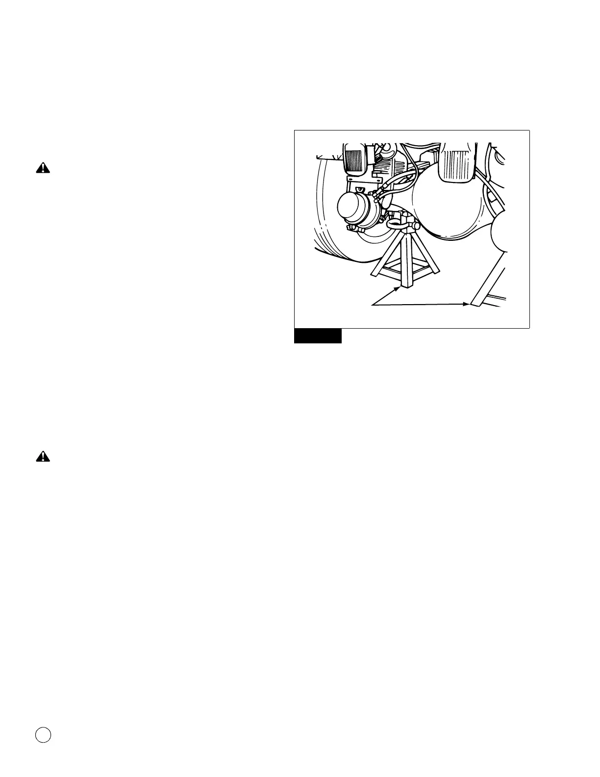
4. Place jackstands under each spring seat of the axle to hold the
vehicle in the raised position. Figure 3.1.
Figure 3.1
5. Remove the plug from the bottom of the axle housing and drain
the lubricant from the assembly.
6. Disconnect the driveline universal joint from the pinion input
yoke or flange on the carrier. Figure 3.2.
Figure 3.1