2 Introduction
5
Meritor Maintenance Manual MM-15103 (Issued 07-17)
Figure 2.4
Figure 2.4
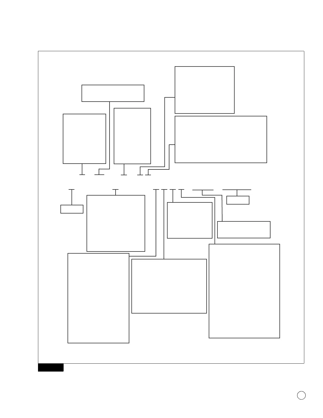
Meritor MS-13X Drive Axle Model Nomenclature
M x - xx - x x x x x x x x x - x x x - x x x x
4012320a
Housing Wall
0 = Cast
1=TBD
2 = 0.31 in. (8 mm)
3 = 0.37/0.39 in. (9.5/10.0 mm)
4 = 0.43 in. (11 mm)
5 = 0.50/0.51 in. (12.7/13.0 mm)
6 = 0.56 in. (14.3 mm)
7=TBD
8 = 0.63 in. (16 mm)
9=TBD
Relative Gearing
Size or Series
0 = No Gearing
1 = 292/347
2 = 337/387
3 = 341/355
4 = 381/432
5 = 415/432
6 = 432/457
7 = 457
8 = 460/498
GAWR
xx = GAWR (000) Pounds or Tons
(dependent on mfg. location)
Axle Model Type
S = Single Rear (Solo)
D = Fwd Rear w/IAD
N = Fwd Rear less IAD
P = Fwd Rear w/Pump
R = Rear Rear
T = Tandem Drive
Z = Tridem Drive
C = Coach
H = High Entry
M = Meritor
Specification Number
Includes: TRACK, PARKING
BRAKE, OTHER.
Ratio 1
Axle Type
0 = No Carrier
1 = Single Speed
2 = Two Speed
3 = Helical Double Reduction
4 = Salisbury
5 = Planetary Double Reduction
6 = Planetary Hub Reduction
7 = Portal
8 = Bevel Hub Reduction
9 = Single Speed with Torque
Output Limited Engine
M S - 2 1 - 1 3 X 5 D B B N Q - 1 2 3 - 3 5 5
Carrier Variation
A = Aluminum
B = Aluminum/Ductile Amboid (Tandem Split)
C = Ductile/Ductile Amboid (Tandem Split)
D = Ductile Rear, Hyboid
E = Aluminum/Ductile (Tandem Split)
F = Ductile Amboid/Ductile Hypoid (Tandem Split)
M = Ductile Rear, Amboid
N = No Carrier
R = Ductile Front Drive Axle Carrier, Right Hand
MFG Location
A = Australia/Asia/Africa
E = Europe
N = North America
S = South America
T = Telma Retarder
(U.S.A.)
Brake Type
B = “B” Frame Brake
C = Air Disc Brake
D = Wedge Brake, Dual Air Chambers
E = Wedge Brake, Dual Hydraulic
Cylinders
F = Wedge Brake, Single Hydraulic
Cylinder
G = DuraPark
®
Hydraulic Drum
H = Quadraulic™ Disc
K = EX+™ Air Disc
L = Q+™ Cam Brake
N = None
P = “P” Series Cam Brake
Q = “Q” Series Cam Brake
R = Cast+™ Brake
S = Wedge Brake, Single Air Chamber
T = “T” Series Cam Brake
V = Simplex Air Cam Brake
W = “W” Series Cam Brake
Z = Non-Meritor Brake
Main Differential Nest Type
A = DCDL/Standard (Tandem
Split)
B = Special Differential
C = Driver Controlled Differential
Lock — DCDL
D = DCDL/NoSPIN
®
(Tandem
Split)
E = Standard/DCDL (Tandem
Split)
F = Standard Differential
G = Standard/NoSPIN
®
(Tandem Split)
H = High Traction Differential
J = NoSPIN
®
/DCDL (Tandem
Split)
K = NoSPIN
®
/Standard (Tandem
Split)
L = No Differential
N = NoSPIN
®
Wheel End/Brake Attachment
A = Conventional Spindle/Conventional
Brake
E = Unitized Spindle/Conventional Brake
J = Conventional Spindle/Integral Brake
L = Conventional L Spindle/Conventional
Brake
N = Unitized Spindle/Integral Brake
R = Conventional R Spindle/Conventional
Brake
S = Bolt on Conventional Spindle/
Conventional Brake
NOTE: The term “Tandem Split” refers to
when there is a difference between the
Forward axle and Rear axle of the Tandem
or Tridem axle set when the Tandem or
Tridem axle set part number is used. The
value to the left of the “/” references the
Forward axle, and the number to the right
of the “/” references the Rear axle. For
information related to the Middle axle of a
Tridem axle set part number, refer to the
Bills of Material.