5 Assembly and Installation
33
Meritor Maintenance Manual MM-15103 (Issued 07-17)
Figure 5.30
Correctly install the bearing caps into their original locations
on the carrier. Do not force the bearing caps into position,
which can damage the carrier. If the bearing caps are not
installed correctly, the bores and threads in the cap will not
match the carrier. Damage to the adjusting rings by
cross-threading can result.
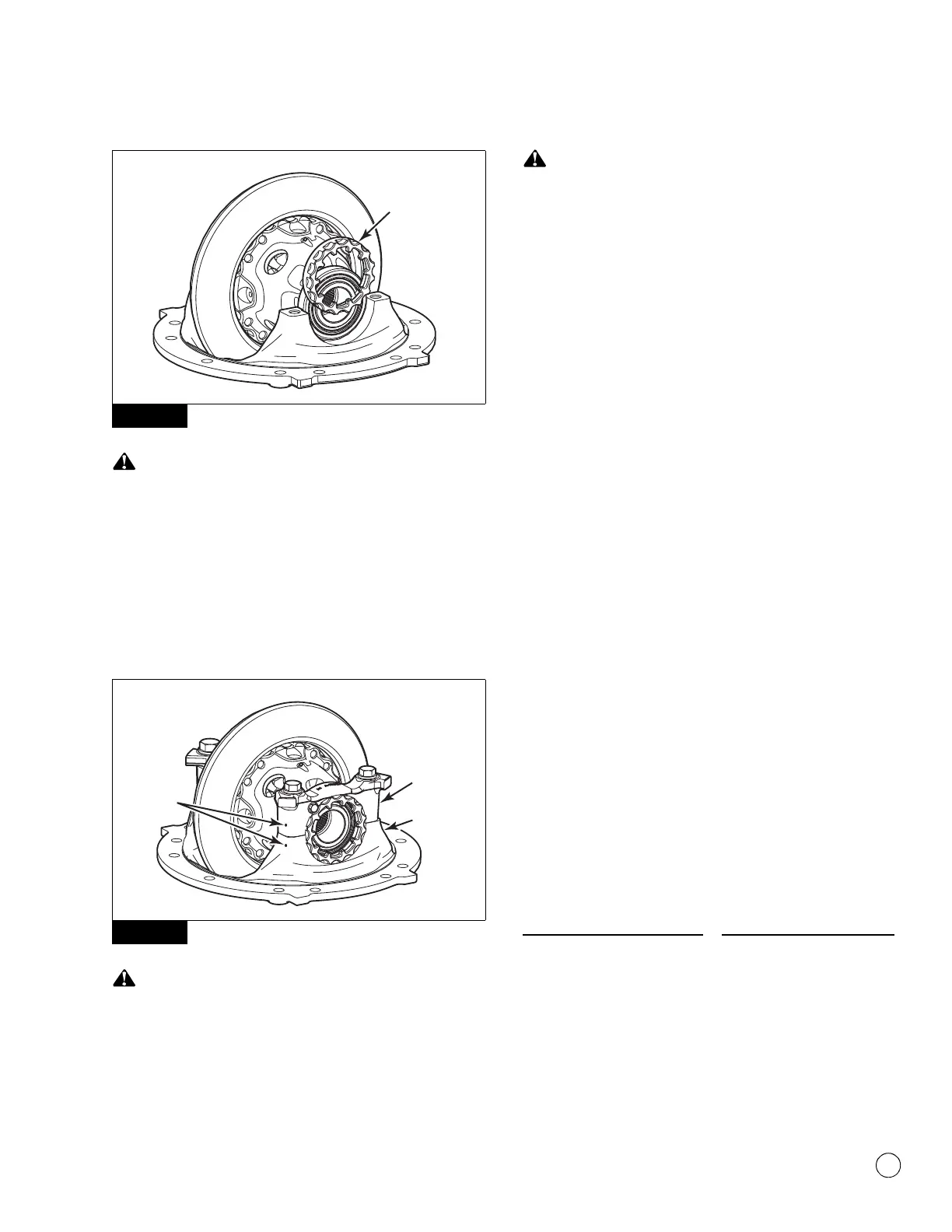
5. Install the bearing caps over the bearings and adjusting rings in
the correct location as marked before removal. Figure 5.31.
Figure 5.31
Use a brass or synthetic mallet for assembly and disassembly
procedures. Do not hit steel parts with a steel hammer. Pieces
of a part can break off. Serious personal injury and damage to
components can result.
Correctly install the bearing caps into their original locations
on the carrier. Do not force the bearing caps into position,
which can damage the carrier. If the bearing caps are not
installed correctly, the bores and threads in the cap will not
match the carrier. Damage to the adjusting rings by
cross-threading can result.
6. Use a light leather plastic or rubber mallet to seat each bearing
cap. The caps must fit easily against the bearings, adjusting
rings and carrier. Do not force the bearing caps into position.
앫 If the bearing caps do not correctly fit into position:
Check the alignment of the match marks between the caps
and carrier. Remove the caps and repeat Step 4 through
Step 6.
7. Hand-tighten the adjusting rings against the bearing cups to
position the ring gear to the pinion with 0.012-inch (0.3 mm)
backlash.
8. Install the capscrews and washers that secure the bearing
caps to the carrier. Tighten the capscrews to 25 lb-ft (34 N폷m).
@
Do not install the capscrews and washers that secure the
bearing adjusting rings in position. After the ring gear is
installed, you must adjust the backlash of the ring gear, inspect
the tooth contact patterns, then adjust the preload of the
differential bearings before the capscrews and washers are
installed.
Adjustment of Pinion Shim Pack and
Backlash for Contact Pattern
Ring Gear Backlash
Table B: Specifications
After checking the tooth contact patterns for top to root position, the
backlash can be readjusted within the specification limits for toe to
heel position, if needed. To change the location of the pattern, use
the following procedures.
Figure 5.30
Figure 5.31
4011960a
CARRIER
CAP
CARRIER
LEG
MATCH
MARKS
Backlash Setting for New
Gear Sets
Backlash Setting Range for
Used Gear Sets
0.012-inch (0.30 mm) 0.008-0.018-inch
(0.20-0.46 mm)