5 Assembly and Installation
39
Meritor Maintenance Manual MM-15103 (Issued 07-17)
Figure 5.52
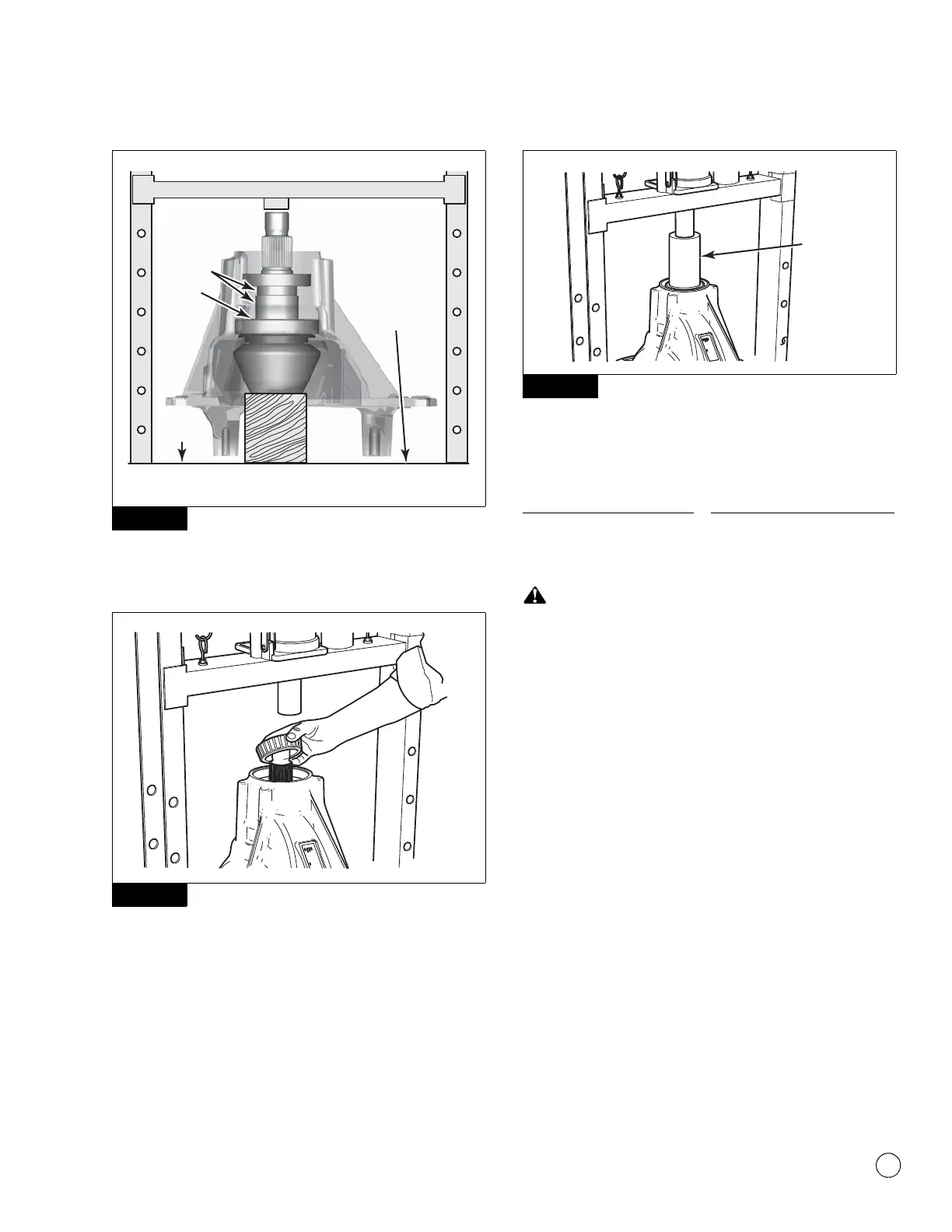
7. Install the outer bearing cone onto the pinion stem.
Figure 5.53.
Figure 5.53
8. Using a sleeve that is the same size as the bearing cone, press
the bearing onto the pinion shaft until it is fully seated in the
carrier. Figure 5.54.
Figure 5.54
Check Pinion Bearing Preload
Table C: Specifications
Do not install tight-fitting yokes or flanges on the shafts using
a hammer or mallet. A hammer or mallet will damage the yoke
or flange.
1. For the purpose of gauging preload, install a used yoke or
flange that fits loosely on the shaft. Do not install the intended
service yoke or flange for this procedure. Align the splines of
the test yoke or flange with the shaft splines. Slide the yoke or
flange over the shaft splines until seated.
2. Install the nut onto the drive pinion.
3. Fasten a yoke or flange bar to the input yoke or flange. The bar
will hold the drive pinion in position when the nut is tightened.
4. Tighten the nut onto the drive pinion to the correct torque
value. Refer to Table H in Section 7.
5. Remove the yoke bar.
6. Attach a torque wrench onto the drive pinion nut. Rotate the
drive pinion and read the value indicated on the torque wrench.
7. If the preload or torque of the pinion bearings is not within
specification, remove the drive pinion assembly from the
carrier. Replace the variable spacer to increase or decrease
preload. Refer to the procedure in this section. Repeat Steps 1
through Step 6 to recheck preload.
Figure 5.52
Figure 5.53
4011978b
Carrier should
not touch
the surface
of the press.
SPACERS
BLOCK OF WOOD
SUPPORTING PINION
SHIMS
PRESS
SURFACE
Figure 5.54
New pinion bearings 30-60 lb-in (3-6 N폷m)
Used pinion bearings in good
condition
20-50 lb-in (2.25-5.65 N폷m)
4011980a
SLEEVE