5 Assembly and Installation
35
Meritor Maintenance Manual MM-15103 (Issued 07-17)
The drive side of a hypoid is the convex side of the ring gear teeth.
The drive side always takes precedence over the coast side; but the
coast side should be evaluated as well. Figure 5.37.
Check Gear Set Tooth Contact Patterns
1. Apply a marking compound, Multan
Gear Mark™ 39SY201
or equivalent, onto approximately 12 gear teeth of the ring
gear. Rotate the ring gear so that the 12 gear teeth are next to
the drive pinion. Figure 5.36.
Figure 5.36
2. Rotate the ring gear FORWARD and BACKWARD so that the 12
gear teeth go past the drive pinion six times to get the contact
patterns. Repeat if needed to get a more clear pattern.
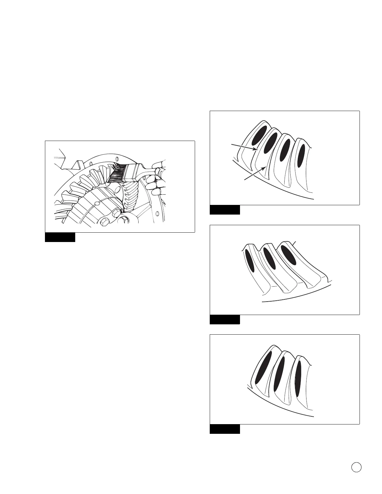
3. Look at the contact patterns on the ring gear teeth. Compare
the patterns to Figure 5.37, Figure 5.38, Figure 5.39,
Figure 5.40, Figure 5.41, Figure 5.42, Figure 5.43 and
Figure 5.44.
The toe-to-heel position of the contact pattern on a good
hand-rolled gear set is toe to toe-center on both sides.
Figure 5.37 and Figure 5.38.
NOTE: When the carrier is in operation under load, a good
contact pattern will extend approximately the full length of the
gear tooth. The top of the pattern will be near the top of the
gear tooth. Figure 5.45 and Figure 5.46.
The location of a good hand-rolled contact pattern for a used
gear set will generally follow the new criteria, although the
pattern may be narrower or the center may not be filled in.
A high-contact pattern indicates that the drive pinion was not
installed deep enough into the carrier. A low-contact pattern
indicates that the drive pinion was installed too deep in the
carrier.
앫 If the contact patterns require adjustment: Continue by
following Step 4 to move the contact patterns between the
top and root of the gear teeth.
앫 If the contact patterns are centered top to root of the
gear teeth: Proceed to Step 5.
Figure 5.37
Figure 5.38
Figure 5.39
Figure 5.36
Figure 5.37
Figure 5.38
Figure 5.39
4012515a
GOOD HAND-ROLLED
PATTERN
CONCAVE
ROOT
TOP
4008132a
GOOD HAND-ROLLED
PATTERN
CONVEX
4008133a
HIGH PATTERN (BAD)
CONCAVE