MM-IM User Guide
14
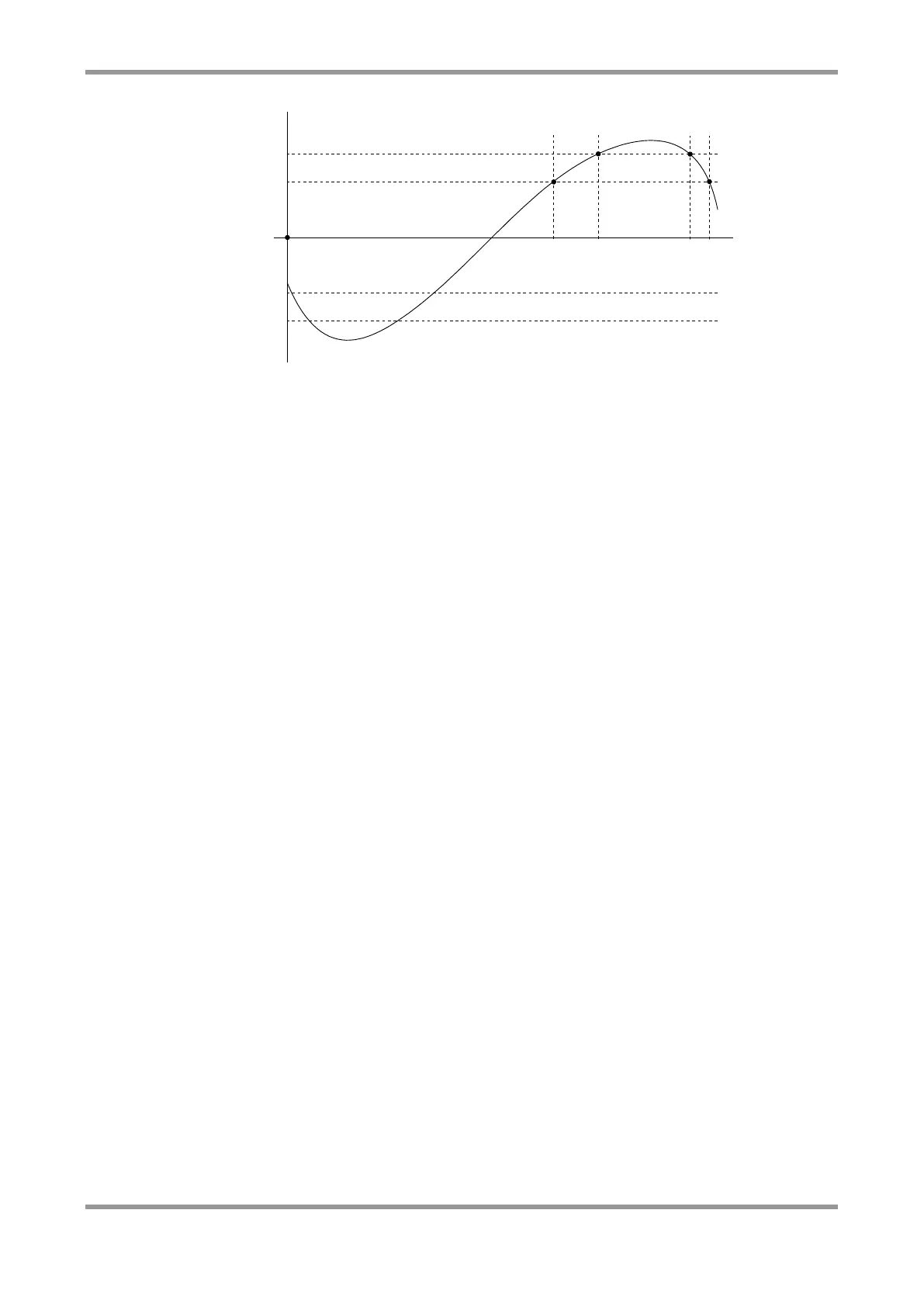
LoLo setpoint
HiHi setpoint
Lo setpoint
Hi setpoint
0
t2t1
t4t3
Figure 1: Alert Level Example
The configuration shown here is a typical one, with the HiHi and LoLo setpoints configured
slightly outside the corresponding Hi and Lo setpoints. Technically all four setpoints are
completely independent but Master Control will normally enforce the order
LOLO<LO<HI<HIHI.
During AI alert processing, the current value of each AI is compared with each of the four
alert setpoint levels for that AI. Ignoring level and time deadbands for the moment, if the
current value is equal to or greater than either of the Hi or HiHi setpoints, then the
corresponding
Hi Level
or
HiHi Level
alert is raised. Similarly, if the level is equal to or less
than either of the Lo or LoLo setpoints, then the corresponding
Lo Level
or
LoLo Level
alert
is raised. Again ignoring level and time deadbands, if the current value goes back within
the setpoint then the corresponding alert is immediately cleared.
Hence in the example illustrated in Figure 1, the
Hi Level
alert is raised at time t1 and
cleared at time t4, whilst the
HiHi Level
alert is raised at time t2 and cleared at time t3.
Now all measured analogue signals will exhibit minor variations about a nominal value.
This means that as an analogue value approaches one of the setpoints the MM-IM is likely
to see a very large number of duplicate alerts being raised and cleared as the value
fluctuates about the setpoint level. To minimise this problem, each AI can be
independently configured with a level deadband and a time deadband.
With just level deadband values in place, the current value must still equal or exceed the
setpoint value before the alert is actually raised. To clear the alert the current value must
fall back below the setpoint value
minus
the alert level deadband value. This situation is
illustrated by Figure 2:
 Loading...