Table of contents
761 Compact IC
VI
List of figures
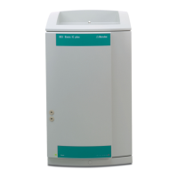
Fig. 1: Front of the 761 Compact IC .......................................................................... 3
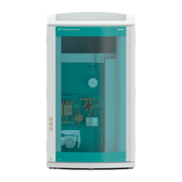
Fig. 2
: Rear of the 761 Compact IC........................................................................... 4
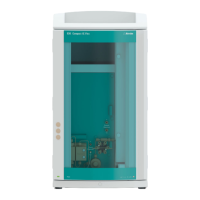
Fig. 3
: Interior of the 2.761.0010 Compact IC ........................................................... 6
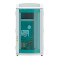
Fig. 4
: Interior of the 2.761.0020 Compact IC ........................................................... 8
Fig. 5
: Connecting diagram for 2.761.0010 Compact IC without suppressor........ 14
Fig. 6
: Connecting diagram for 2.761.0020 Compact IC with suppressor............. 14
Fig. 7
: Connectors for capillaries............................................................................. 17
Fig. 8
: 6.2821.000 Filter unit PEEK .......................................................................... 18
Fig. 9
: Setting the mains voltage ............................................................................. 20
Fig. 10
: Connection of the pulsation dampener........................................................ 26
Fig. 11
: Connection of eluent bottle........................................................................... 28
Fig. 12
: Installation of precolumn cartridges with cartridge head............................. 32
Fig. 13
: Installation of precolumn glass cartridges with cartridge holder ................. 34
Fig. 14
: Installation of column without suppressor.................................................... 37
Fig. 15
: Installing pump tubings ................................................................................ 39
Fig. 16
: Connection of the separating column with suppressor ............................... 40
Fig. 17
: Connection of supply bottles........................................................................ 42
Fig. 18
: Connections at suppressor module ............................................................. 43
Fig. 19
: Components of the pump head ................................................................. 177
Fig. 20
: Replacement of the piston seal 112 .......................................................... 177
Fig. 21
: Components of inlet valve 113 and outlet valve 114................................. 179
Fig. 22
: Assembling the suppressor........................................................................ 183