maxPAC Hardware Reference Guide
Metso Automation MAX Controls Inc. • 277596 •
11-12
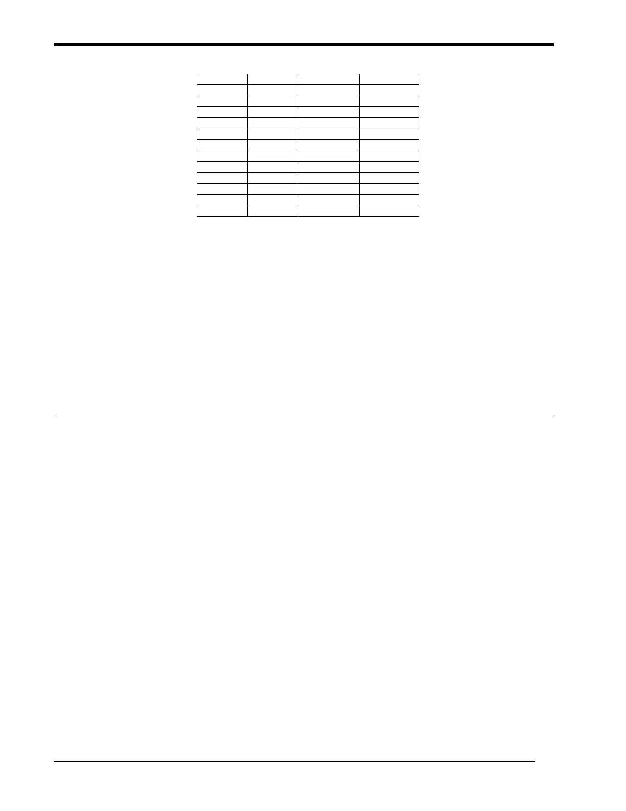
229 750 16 22
305 1000 14 20
457 1500 12 17
610 2000 10 15
762 2500 9 14
914 3000 8 13
1067 3500 7 12
1219 4000 6 11
1372 4500 6 10
1524 5000 5 9
1676 5500 4 9
1829 6000 4 8
2000 6500 4 8
Links can be in series or in parallel, the preferred configuration approach. In
a parallel link, a star approach, each remote location's BEM is connected to a
BEM located on the electrical bus with the DPU.
In a series link, the links can be configured such that one BEM and DPU
connects to a remote's BEM and its rack. This rack then contains another
BEM, which is then connected to a second remote's rack with its BEM. This
configuration approach introduces time delays, which will limit the number
of supported modules. Consult the factory if more than two links are on one
DPU.
Ensuring Link Availability
To ensure link availability, installations may include multiple levels of
redundancy. In configurations using only a single DPU, redundant cables
ensure availability. The loss of either cable pair will automatically route the
signal to the alternate cable pair. Only a momentary loss of the remote I/O,
(milliseconds), will occur while the Extender switches over to the inactive
cable.
To ensure optimal availability, each cable pair should be routed separately to
minimize the probability of damage to both cables. With separate cables, in
the event a cable should break or fail, a second cable is still available.
In configurations using redundant DPUs, each DPU can have its own bus
Extender to the remote location. Any single failure of the Extender or cable
will not result in loss of operation, and the replacement of the failed
component can occur without loss of service.
A failure in the remote location will only affect the remote I/O modules
associated with the remote Extender.
Refer to the front-panel LEDs and a digital output to identify fault conditions
detected by the link, specifically loss of lock and receive error.