maxPAC Input/Output Subsystem
Metso Automation MAX Controls Inc. • 277596 •
1-11
P11
P9
P10
P11
P9
P11
P9
P11
P9
P11
P9
P10
P11
P9
P10
P11
P9
P11
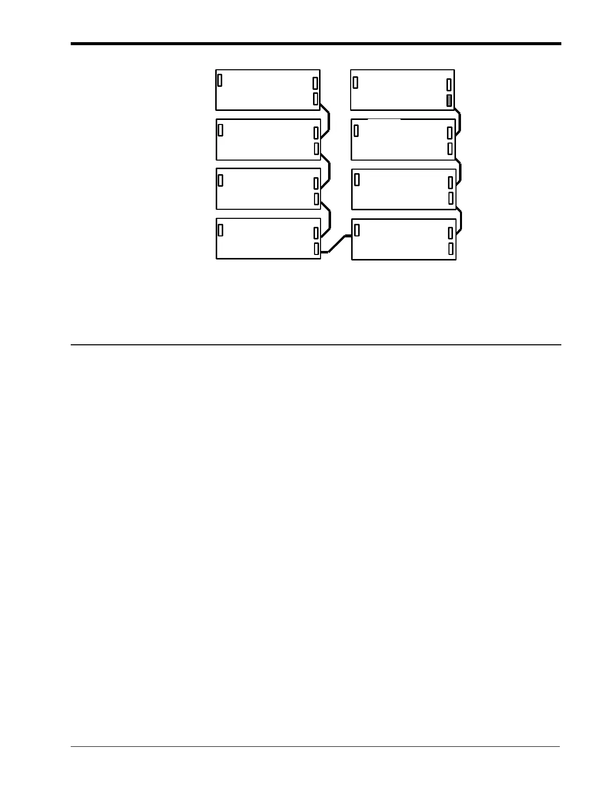
Figure 1-5. Interconnecting Adjacent I/O Cabinets
Module Mounting Considerations
I/O Modules
As you determine how modules are positioned in a cabinet, give some thought
to the signal levels that are to be wired to the modules. High and low signal
levels and AC and DC wiring should be kept separate. In general, wherever
possible, modules receiving the same type and level of signals should be
grouped together, with similar signal types arranged in vertical columns.
DPU Modules
The DPU must be mounted in its own special six-wide I/O chassis in the
right most position since the DPU is wider than the I/O cards and requires
good air flow. Likewise, when using a second DPU for backup, it must be
inserted in the same six-wide chassis style mounted beneath the primary
DPU.
Before mounting I/O modules, you should complete power and grounding
and field wiring and any I/O module preparation and adjustment. See
appropriate chapters in this publication to check correct addressing and
jumper selection on the modules.
Before installing an I/O module in the right-most position of a chassis
assembly, make sure the +24 Vdc is connected to the chassis assembly as
well as the I/O bus cable. Additionally, connect the cabinet frame ground to
the Model IOP I/O chassis assembly before installing an I/O module in the
extreme left position of a chassis assembly. Refer to "Cabling, Power, and
Ground Wiring."