maxPAC Hardware Reference Guide
Metso Automation MAX Controls Inc. • 277596 •
6-4
either reset or remain in their last state depending on the position of the
onboard program jumper.
Module calibration is done automatically at power up following startup
diagnostics.
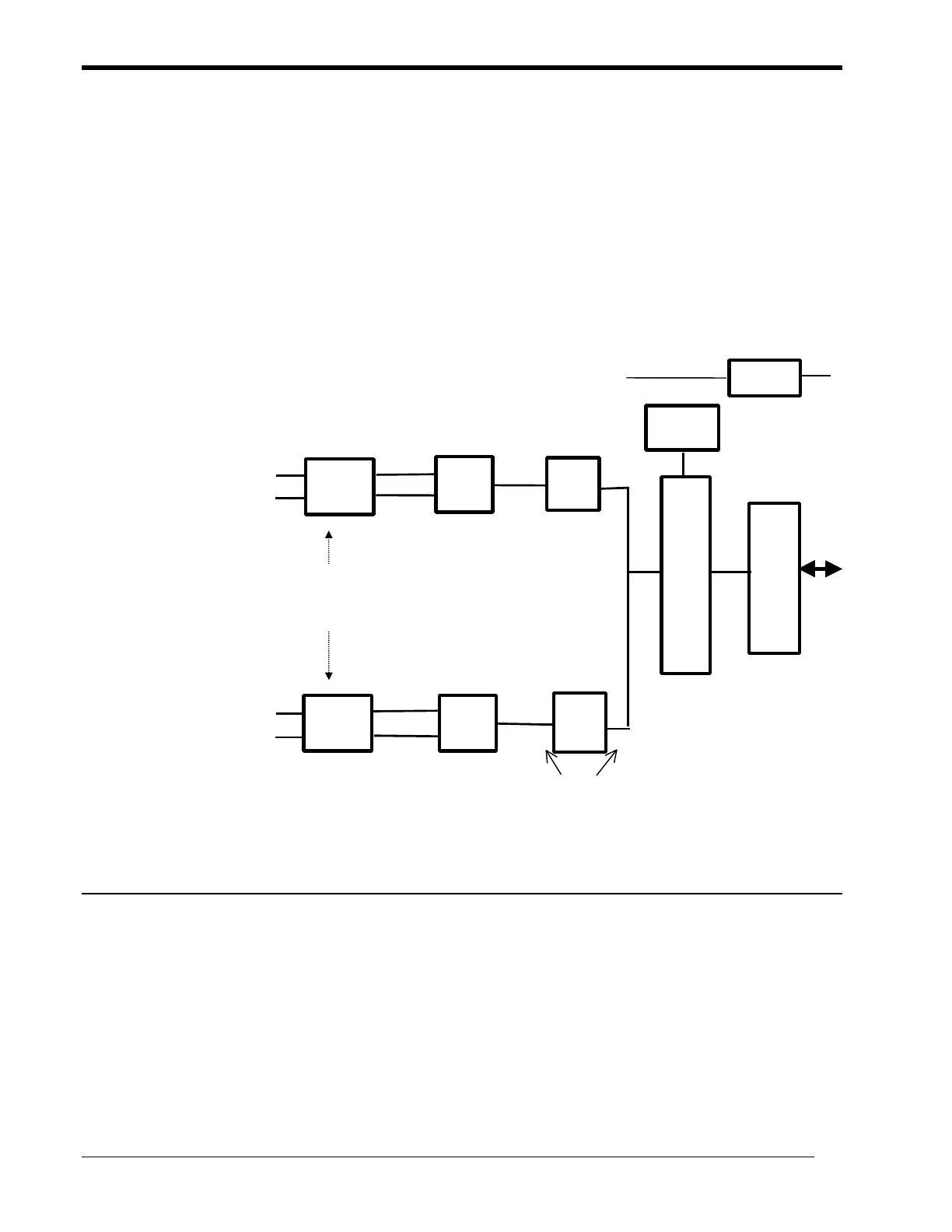
The 24-Volt loop supply is available to the module from the backplane. All
the outputs are connected to the loop supply.
FLASH
FPGA
I/O Bus
Regulator
24V
uC
OPTO
optical isolation
field to logic
D/A 1
D/A 8
Channel 1
Channel 8 OPTO
4-20 ma
out
4-20 ma
out
Powered from field
24V supply
Diagnostics
The module executes diagnostics on power up. When an error is detected on
power-up or during online operation, the front-panel green LED, labeled
Active, blinks the first digit at a slower rate and the second digit at a faster
rate. During normal operation the active LED is on continuously or flashes at
a steady one-second rate when the module is not being scanned. The
diagnostic codes are as follows: